131 Eisenhower Lane North
Lombard, IL 60148
630.268.0010 / 1.800.251.2408
P/N 53-00684-200 Rev. A 071301
www.Intellitecsve.com
Intellitec
INSTALLATION & SERVICE MANUAL
TM
50 AMP Smart Energy Management System Model 900
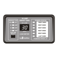
DISPLAY PANEL
The Display Panel can be mounted remotely and connects to the main unit with a light gauge, four-wire cable. Six Power
Status LED's indicate power is applied to those loads. These LED's are on when the power is applied. The Load Meter
has a two-digit display to indicate the amount of current actually being drawn by all the appliances in the coach.
Four Service Type LED's indicate the source for 120/240 VAC power. Three of these sources are automatically detected
and indicated by the EMS, namely: Gen Set service, 50 Amp 240 VAC service, and 30 Amp 120 VAC service.
When 120VAC shore power is first applied, the system will always be in the 30
Amp mode. The 30/20 Amp indicator LED will be on when the system is in the 30
Amp mode.The 20 Amp service mode is not automatically detected and the
operator must manually select the 20 Amp mode, when 20 Amp service is
available. The Service Select button allows the current threshold to be set to
either 30 Amps or 20 Amps, to match the incoming service.
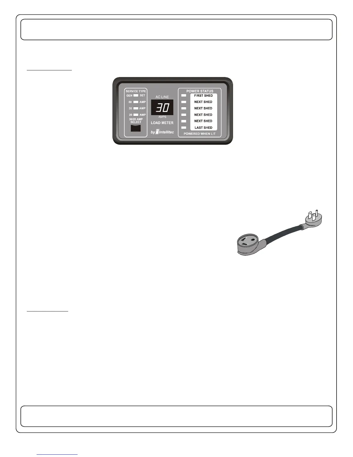
If the pictured adaptor is used on the incoming service, press the service select
button to select the 20 Amp mode. Momentarily pressing this button again will
switch the system back to the 30Amp mode.
The Display Panel can also be used to display the value of current stored in memory for each of the six loads. To display
the values of current stored in memory for each of the six loads, push and hold the Service Select button. The uppermost
LED will illuminate and the stored value will appear on the Load Meter. Pushing Service Select again, will cycle to the next
load. After the last stored value has been displayed, the Load Meter will return to normal operation and display total
current draw.
INSTALLATION
The Control Module:
The first step when installing an EMS is to determine which loads will be controlled and in what order they will be shed. A
typical scheme would be to control the two air conditioners, the water heater and the washer/dryer. With these loads, the
first load to be shed should be the water heater, as it's loss of operation would be the least noticed (it would switch to
operate on gas, if needed). The next would be the bedroom air; the third would be the washer dryer and finally the main air.
Choosing this sequence would provide the least inconvenience to the occupants. User discretionary loads, such as
microwave ovens, coffee pots, hair dryers, etc. should never be considered as EMS controlled loads.
50 AMP
SMART EMS
 Loading...