131 Eisenhower Lane North
Lombard, IL 60148
630.268.0010 / 1.800.251.2408
P/N 53-00684-200 Rev. A 071301
www.Intellitecsve.com
Intellitec
INSTALLATION & SERVICE MANUAL
TM
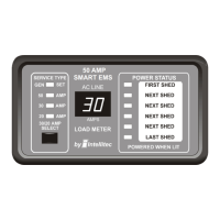
50 AMP Smart Energy Management System Model 900
Distribution Panel:
The EMS Distribution Panel should be installed in a convenient location where it can get air circulation to keep it from
over heating. There should be a minimum of 7" of depth behind the mounting surface to provide enough room for the
box and wiring.
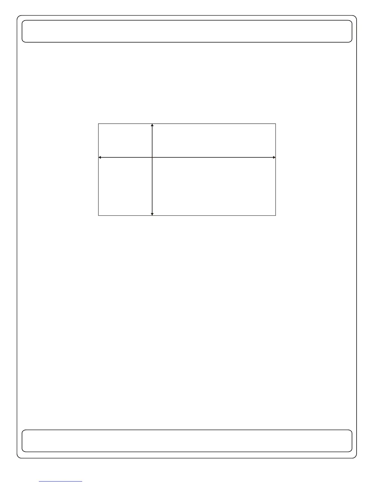
A hole should be cut in the mounting panel as shown.
This opening must be cut carefully to be sure the mounting screws will have enough wood to hold and there is enough
clearance around the box for the front cover screws.
The wiring to the box should be routed through the holes in the back and secured using approved cable connectors. The
wires should be copper conductors ONLY, with the appropriate size and insulation to meet N.E.C.
The main supply cable should be brought through the large hole in the lower center of the box and secured with an
appropriate connector. The "LINE 1" and "LINE 2" supply mains should be connected to the corresponding main breaker.
The main ground lead should be connected to the nearest GROUND bar terminal strip. The current sensor should be
mounted in a knock-out hole near the insulated NEUTRAL block, so that the signal leads from the current sensor exit the
rear of the box. These signal wires should be routed through the lower right hole into the low voltage section of the EMS
and connected to J3, a 2 pin connector on the low voltage side of the Control Module.
The main NEUTRAL wire should be routed through the CURRENT SENSOR and connected to an appropriate position on
the insulated NEUTRAL block.
There are 8 positions for the circuit breakers in the box. The circuit breakers can be single or dual types. The breakers in
the two center positions must be 50 Amp to be used as the Main Breakers.
The following breakers are suitable for MAIN and BRANCH breakers:
Bryant - BR, BD, GFCB, Filler Plate FP-1B
ITE Gould - QP, QT, Filler Plate QF3
The replacement circuit breakers must be of the same type and rating.
9 1/8” +/- 1/8”
15 ½” +/- 1/8”
DISTRIBUTION PANEL CUTOUT
 Loading...