131 Eisenhower Lane North
Lombard, IL 60148
630.268.0010 / 1.800.251.2408
P/N 53-00684-200 Rev. A 071301
www.Intellitecsve.com
Intellitec
INSTALLATION & SERVICE MANUAL
TM
50 AMP Smart Energy Management System Model 900
SYSTEM TEST:
All the 120 volt loads should be turned off or disconnected. Both 120VAC 30 Amp shore power (an adapter must be used
to connect the 30A source) and 12 volt DC power should now be applied to the system. Initially, there will be a two-minute
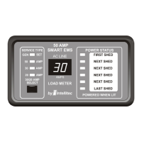
start-up delay. When this is done, the relays should be heard pulling in at approximately one second intervals . On the
Display Panel, the numeric display should read "0", the six Power Status LED's should come on, and the "30 Amp" Service
Type LED should light. A clamp-on type ammeter should be used to measure the current being supplied by the 30 Amp
shore power cord.
Connect or turn on one of the controlled AC loads. It should operate and the numeric display or the clamp-on ammeter
should show the amount of current that load is drawn. Turn that appliance off and repeat this with each of the others.
To test the load shedding, turn on all the controlled appliances. The total current drawn should exceed 30 Amps.
(If not, add additional loads to the non-controlled receptacles.) When the total amount of current exceeds 30 Amps, the
loads should begin to turn off to bring the total below 30 Amps.
FUSES
F1 - 3 Amp ATO type, for EMS Control Module circuitry only. DO NOT replace with a fuse of higher rating. This could
result in severe damage to the circuitry or create a possible fire hazard.
EMS CONTROL MODULE PLUGS, PINS, AND FUNCTIONS:
J1 = 2 pin Molex KK-100 connector - HI-POT TEST Power Up
Pin Function
1 Hi-Pot Override
2 Hi-Pot Override
J2 = 3 pin Amp Mate-n-Lok connector - Power connector
Pin Function
1 +12 Volts Supply
2 +12 Volts Gen-Set Run input
3 Chassis Ground
J3 = 2 pin Molex KK-156 - Current Sensor Connector
Pin Function
1 Current Sensor Input
2 Current Sensor Input
J4 = 6 pin Amp Mate-n-Lok connector - Control Relays 5 & 6 contacts
Pin Function
1 Relay 5 N.O.
2 Relay 5 COM.
3 Relay 5 N.C.
4 Relay 6 COM.
5 Relay 6 N.C.
6 Relay 6 N.O.
 Loading...