131 Eisenhower Lane North
Lombard, IL 60148
630.268.0010 / 1.800.251.2408
P/N 53-00684-200 Rev. A 071301
www.Intellitecsve.com
Intellitec
INSTALLATION & SERVICE MANUAL
TM
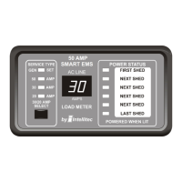
50 AMP Smart Energy Management System Model 900
EMS CONTROL MODULE PLUGS, PINS, AND FUNCTIONS (continued)
J5 = 4 pin Molex KK .156 - Display Panel Connector Mating Housing Molex 09-50-3041
Pin Function
1 Power
2 Data
3 Ground
4 30/20 Amp Select Line
J6 = 5 Position Terminal Block
Term Function
1 From Circuit Breaker for Relay 2 (Must be connected to a LINE 2 Breaker)
2 Output of Relay 2
3 From Circuit Breaker for Relay 1 (Must be connected to a LINE 1 Breaker)
4 Output of Relay 1
5 Neutral
J7 = 4 Position Terminal Block
Term Function
1 Output of Relay 3
2 From Circuit Breaker for Relay 3
3 Output of Relay 4
4 From Circuit Breaker for Relay 4
NOTE: J6 and J7 terminal blocks - Will accept up to 12 GA or 14 GA copper wire ONLY.
 Loading...