1485 Jacobs Rd.
Deland, FL 32724
386.738.7307
P/N 53-00549-100 Rev. C 032619
www.intellitec.com
Intellitec
SERVICE MANUAL
SMART EMS
TM
CAUTION
SMART EMS
CIRCUIT PROTECTION
ENERGY MANAGEMENT
CONTROLLED LOADS
EMS
The SMART EMS is a centralized power switching, fusing, and distribution center. Power from the 120 volt
power source is fed into the box. The potential of lethal electrical shock is present in this box. Inadvertent
shorts at this box could result in damage and/or injury. All servicing of this box should be done by a
qualified Service Technician.
Diagnostic tools required: Low current Test Light, Accurate Voltmeter (digital readout
preferred), Clamp-onAC ammeter.
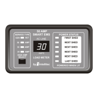
The provides main and branch circuit protection control of up to four selected appliances. The
control helps to limit the total current draw of all the appliances in the RV at or below 30 Amps provided by the main
power feed.
Circuit protection for ALL the 120 VAC loads is offered by standard, reset-able circuit breakers, provided by the
installer. There are four positions available for circuit breakers. These may be single or dual units. One of these
breakers must be a 30 Amp unit to act as the Main breaker for the entire system. The 120 volt power is brought into
the box from either a shore cord or generator. The line side of this cable is fed through the magnetically coupled
current transformer located on the EMS pcb, and connected to a 30 Amp circuit breaker that acts as the Main
breaker. This breaker back-feeds power into the circuit breaker bus to feed power to the branch breakers. These can
be either single or dual circuit types. All the loads in the RV are fed from the branch breakers.
The current entering the main circuit breaker is routed through the magnetically coupled current sensor. This sensor
measures the current flowing through the main breaker, which is the total amount being drawn by all the 120 volt
appliances in the RV. When this current exceeds 30 Amps (20 Amps if the threshold has been set lower), the EMS
will turn off the controlled loads in an effort to bring the total current to the limit of the incoming service.
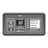
The system offers control of up to four 120 VAC powered loads. Loads that are to be controlled are connected to one
of the relay circuits of the . There are five total control relays in the EMS. ONLY 4 of these can be used in a given
application.
Two of these five circuits have single pole double throw, low voltage relays, with un-dedicated contacts available.
These are intended to control air conditioners or other appliances equipped with low voltage controls or thermostats.
The contacts of the relays are typically wired in series with the thermostats of airconditioners so the EMS turns off
only the compressor. This leaves the fan on to recirculate the air, masking the interruption of the compressor. These
relay circuits could also control other 120 volt appliances if an additional control relay is added externally.
Three of these circuits are 15 Amp relays to interrupt the 120 volt power to the loads. These circuits are intended to
control 120 volt appliances such as water heater, washer/dryer, coffee maker, etc. For the 120 switched loads,
power is routed from the individual branch circuit breakers to one of these 120 volt relays. The controlled load is then
fed from that relay.
TM
only
HOW IT WORKS
TM
and
 Loading...