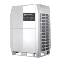
This document is a service manual for the INTENSITY VRF V5X High Efficiency air conditioning system, covering models MV5-X252W/V2ZN1, MV5-X280W/V2ZN1, MV5-X335W/V2ZN1, MV5-X400W/V2ZN1, MV5-X450W/V2ZN1, MV5-X500W/V2ZN1, MV5-X560W/V2ZN1, and MV5-X615W/V2ZN1. It provides comprehensive information on general system details, component layout, refrigerant circuits, control logic, field settings, and diagnosis/troubleshooting procedures.
Function Description
The INTENSITY VRF V5X system is a high-efficiency Variable Refrigerant Flow (VRF) air conditioning system designed for both cooling and heating operations. It utilizes a sophisticated control scheme to manage multiple indoor and outdoor units, ensuring optimal performance and energy efficiency. Key functional components include:
- Compressors: Inverter compressors (A and B) regulate refrigerant flow and pressure, with their rotation speed controlled based on load requirements.
- Electronic Expansion Valves (EXV): These valves control refrigerant flow and reduce pressure, operating in steps from fully closed (0) to fully open (480) based on discharge temperature (cooling) or discharge superheat (heating).
- Four-way Valve: This valve controls the direction of refrigerant flow, closing for cooling and opening for heating.
- Solenoid Valves (SV2, SV4, SV5, SV6):
- SV2 (Liquid Refrigerant Injection): Protects the compressor by spraying liquid refrigerant to cool it if the discharge temperature exceeds 100°C, closing when it falls below 90°C.
- SV4 (Oil Balance): Returns oil to the compressor, opening for 3 minutes every 20 minutes after an initial 200-second run and 600-second close cycle.
- SV5 (Fast Defrosting): Opens during defrosting to shorten the refrigerant flow cycle and quicken the process, closed in cooling mode.
- SV6 (EXV Bypass): Allows refrigerant to bypass expansion valves, open in cooling mode when discharge temperature exceeds the limit, closed in heating mode or standby.
- Oil Separator: Separates oil from gas refrigerant and returns it to the compressor with up to 99% efficiency.
- Accumulator: Stores liquid refrigerant and oil to protect the compressor from liquid hammering.
- High and Low Pressure Switches: Regulate system pressure, stopping the compressor if pressure exceeds upper limits or falls below lower limits. The compressor restarts after 10 minutes.
- DC Fan Motors: Control fan speed based on discharge pressure (cooling) or outdoor heat exchanger pipe temperature (heating).
- Crankcase Heater: Prevents refrigerant from mixing with compressor oil when compressors are stopped, controlled by outdoor ambient temperature and discharge temperature.
The system supports various indoor unit types including one-way, two-way, compact four-way, four-way cassettes, medium static pressure ducts, high static pressure ducts, wall-mounted, ceiling & floor, floor standing, and console units, as well as fresh air processing units and heat recovery ventilators.
Important Technical Specifications
- Outdoor Unit Capacities: The manual details outdoor unit capacities ranging from 8HP (X252W) to 88HP (X2460W) through various single and combination units.
- Combination Ratio:
- Minimum combination ratio: 50%
- Maximum combination ratio (standard indoor units only): 130%
- Maximum combination ratio (fresh air processing units only): 100%
- Maximum combination ratio (fresh air processing units and standard indoor units together): 100% (with fresh air units not exceeding 30% of total outdoor unit capacity).
- Maximum Number of Connected Indoor Units: Varies by outdoor unit capacity, from 13 for an 8HP unit to 64 for units 40HP and above.
- Compressor Current Limitation: Specific current limits for different compressor models (e.g., E705DHD-72: 23A, E655DHD-65: 21A, E405DHD-36: 12A, E405DHD-42: 15A).
- DC Bus Voltage: Normal range between P and N terminals is 585-715V.
- Fan Speed (RPM): Varies by HP and fan (FANA/FANB), with different steps for silent, super silent, standard ESP, medium ESP, and high ESP modes.
- Temperature Sensor Resistance Characteristics: Detailed tables provide resistance values (kΩ) for outdoor ambient/heat exchanger temperature sensors and inverter module temperature sensors at various temperatures (°C).
Usage Features
- Control Modes: The system supports various control modes including cooling, heating, standby, and special controls like oil return and defrosting.
- Operating Priority and Rotation of Compressors: In multi-unit systems, compressors operate in rotation to balance wear and tear. In dual-compressor units, inverter compressor A (BP1) has priority over inverter compressor B (BP2).
- Night Silent Mode: Activated X hours after peak daytime temperature and deactivated after Y hours, with configurable settings (e.g., 6h/10h, 6h/12h, 8h/10h, 8h/12h) to reduce operation sound by up to 15dB.
- Priority Mode Settings: Five options: heating priority (default), cooling priority, VIP priority/voting priority, heating only, and cooling only. VIP priority mode allows a designated indoor unit (address 63) to dictate the system's operating mode.
- Addressing Modes: Supports auto addressing and manual addressing for indoor units, with options for centralized controllers.
- Outdoor Unit Duty Cycling: Prevents compressor burnout due to unbalanced oil levels in multiple outdoor unit systems.
- Oil Return Operation: Automatically initiated after 140 minutes of initial operation and then every 8 hours to recover oil from the piping system.
- Defrosting Operation: Conducted when the outdoor unit heat exchanger performs as an evaporator, controlled by ambient temperature, heat exchanger temperature, and running time.
- Protection Controls: Includes high pressure, low pressure, discharge temperature, compressor current, and inverter module temperature protection to ensure system longevity and safety. Heating mode is disabled if outdoor ambient temperature rises above 25°C.
Maintenance Features
- Digital Display Output: Provides real-time information on unit address, number of indoor units, output metrics, operating mode, fan speed index, temperatures, pressures, currents, and error/protection codes.
- LED Indicators (LED1-LED7): Provide visual cues for power supply, running status, error conditions (communication errors, inverter module errors), and standby status.
- SW2 System Check: Allows technicians to display various system parameters on the DSP2 digital display for diagnostic purposes.
- Error Code Table: A comprehensive list of error codes (E0, E2, E4, E5, E7, E8, xE9, xH0, H1, H2, H3, xH4, H7, H8, yHd, P0, P1, P2, H5, xP3, P4, H6, P5, P9, H9, PL, C7, PP, F0, xF1, dF, d0, xL0-xL9, r1-r3, R1, R2) with their content and remarks for quick identification of issues.
- Troubleshooting Procedures: Detailed flowcharts and steps are provided for each error code, guiding technicians through checks for wiring, sensor connections, power supply, refrigerant levels, component malfunctions (compressors, fans, inverter modules, transformers, rectifiers, capacitors), and blockages.
- Compressor Replacement Procedure: Outlines steps for removing faulty compressors, draining and inspecting oil, checking other compressors, replacing oil separators and accumulators, adding new compressor oil (FV68H), and performing vacuum drying and refrigerant charging.
- Sensor Resistance Tables: Essential for verifying the functionality of temperature sensors by comparing measured resistance values with specified characteristics.
- Warning for Electrical Work: Emphasizes that all electrical work must be carried out by competent, qualified, certified, and accredited professionals in accordance with all applicable legislation, and that power must be off before connecting or disconnecting any wiring.