Do you have a question about the Inter-m R-150 Plus and is the answer not in the manual?
Read manual to familiarize with installation, features, and operation. Original packaging required for returns.
Step-by-step guide for initial setup and operation, including power connection and level adjustment.
Guidance on selecting an appropriate operating environment to ensure performance and service life.
Crucial safety precautions for installation, including electrical safety and environmental considerations.
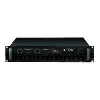
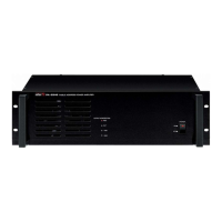
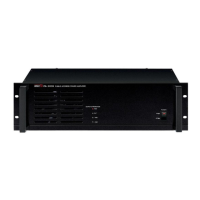
Details for R150, R300, R500 PLUS models: rack space, channels, and power output.
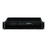
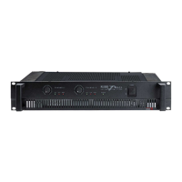
Highlights include 4Ω stereo/8Ω mono stability, 2U rack space, indicators, rack ears, and detachable cord.
One detachable AC power cord is provided for use with this product.
Adjusts input signal level per channel; Channel 1 used in bridge mono mode.
Shows input signal level; should be illuminated during normal operation.
Warns of signal clipping; reduce level if illuminated. Should not be illuminated during normal operation.
Indicates system problems like overheating or low impedance. Reduce volume if illuminated.
Confirms the amplifier is ON and receiving AC POWER; Switch turns amplifier ON/OFF.
Provided for moving and installing into equipment enclosures or racks.
1/4" TRS and XLR connectors for balanced signal input on each channel.
Selects between STEREO and BRIDGED MONO operation modes.
Binding Posts and Locking speaker connectors for outputting audio signals.
Protects amplifier from overload; connects to AC power source.
Suggestions for maintaining proper airflow and cooling in rack installations.
Diagram showing a typical rack setup with amplifiers, fans, and blank panels.
Pinout for balanced XLR connectors: Pin #1 Shield, #2 Positive, #3 Negative.
Pinout for balanced 1/4" TRS connectors: Tip Positive, Ring Negative, Sleeve Shield.
Diagrams for insert points, amp/line input, headphones, and AUX send.
Uses one positive and one negative terminal from the same channel for stereo operation.
Uses positive terminals from both channels; impedance limitation of 8Ω.
Specifies power output for STEREO (8Ω/4Ω) and BRIDGED MONO (8Ω) for all models.
Details frequency response (20Hz-20kHz) and Total Harmonic Distortion (≤0.1%).
Specifies channel separation (≥70dB), residual noise (≤-80dB), and S/N ratio (≥100dB).
Details input sensitivity (0dBm) and indicator functions/colors.
Describes protection features (muting, short circuit, thermal) and power source requirements.
Lists power consumption, weight, and physical dimensions of the amplifiers.
Steps for troubleshooting and contacting warranty provider for service, schematics, and parts.
Compatibility with local power requirements and availability of optional items.
Details on warranty terms, conditions, and how to obtain specific information.