Interflex Datensysteme GmbH 5/7
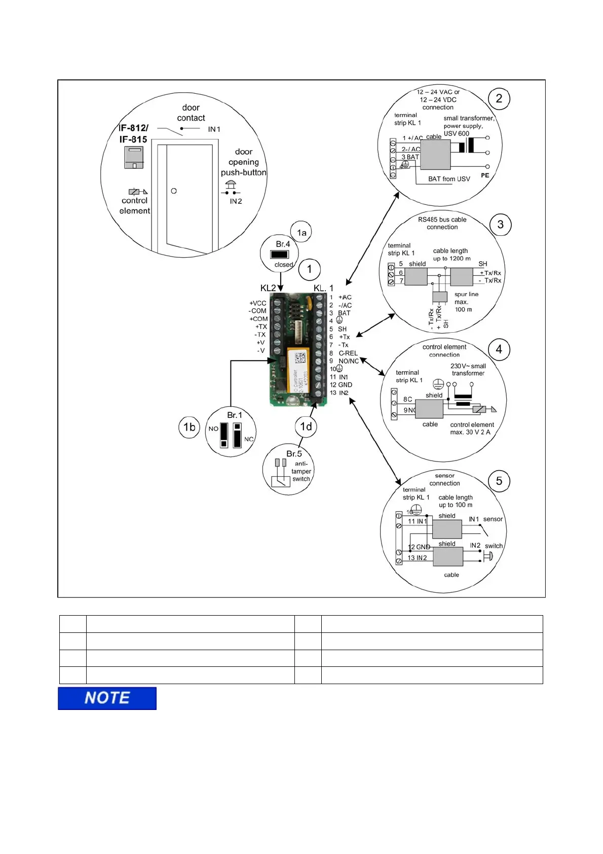
3.7 Controlling Locking Devices with I/O Controller Board
1 I/O controller board (accessories) 2 Power supply connection
1a Br. 4 jumper selection 3 Data cable connection
1b Br.1 relay contact in NO or NC position 4 Connection of electric control element (door opener)
1d Br.5 plug contact for anti-tamper switch 5 Connection of door sensor, handle or NC contact
The I/O controller board allows for access control. The board can switch electric door
openers up to max. 30 V 2 A via an NO or NC contact. It must be separated from the IF-812/IF-815 terminal
and installed in a secured area, e.g. in a Hensel installation box (no. 78-700-0146) or a DIN appliance case.
In order to prevent malfunction and manipulation, the I/O controller board may not be installed in the housing
of an IF-812 or IF-815 terminal.