Interflex Datensysteme GmbH 6/7
3.7.1 Circuit Examples
Power supply (2)
The IF-812/IF-815 terminal can be supplied with 12-24 V AC/DC via the I/O controller board.
Connection of RS485 data cable (3)
The RS485 data cable is connected to terminals 5, 6 and 7. The data cable may have a max. length of 1200
m. If a spur line is connected to the data line, the length of the spur line may not exceed 100 m.
The use of shielded cables is not absolutely necessary, but recommended, in order to
avoid interferences.
Connection of a control element (4)
An actuator, shown as a door opener in the figure, is connected to terminals 8 and 9. The actuator is
controlled by the relay of the I/O controller board and can switch a maximum of 30 V and 2 A. Via the bridge
(1b), the relay contact can be changed from normally open (NO) to normally closed (NC). If two relay outputs
are required, a further I/O controller board is needed.
Connection of sensors (5)
Two sensors can be connected to the I/O controller board. Usually, one door contact and one door opener
are connected. If more than two sensors are required, a second I/O controller board is needed. The bridge
(BR4) must then be removed on the second I/O controller board.
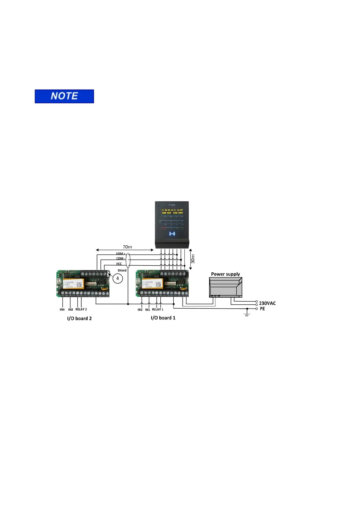
3.7.2 Connecting two I/O controller boards
3.7.3
For technical reasons, the total length of the COM cable is limited to 100 m. The length of the COM cable is
to be reduced as in the example to ensure that a total length of 100 m is not exceeded. The bridge (4) on I/O
controller board 2 must be removed.
3.8 Accessories
The following components can be ordered as accessories:
I/O controller board, order number: 75-700-0141
Power transformer PSU 230 / 20 VAC 1.5 A, order number: 41-10106
Release lever for housing, order number: 50-10137)
 Loading...