ñ Ensure the ceiling is horizontally level, otherwise condensate
water cannot drain.
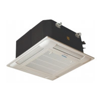
ñ The casing is fixed to the slab with 4 drop rods. The rods
should have two nuts and washers to lock the unit in position.
The Cassette brackets will then hook over the washers.
ñ When lifting the Cassette into position care should be taken
not to lift the unit by the drip tray, which could be damaged.
ñ Lift unit (without the air panel) with care by its four corners
only. Do not lift unit by the condensate drain discharge pipe
or by the piping connections.
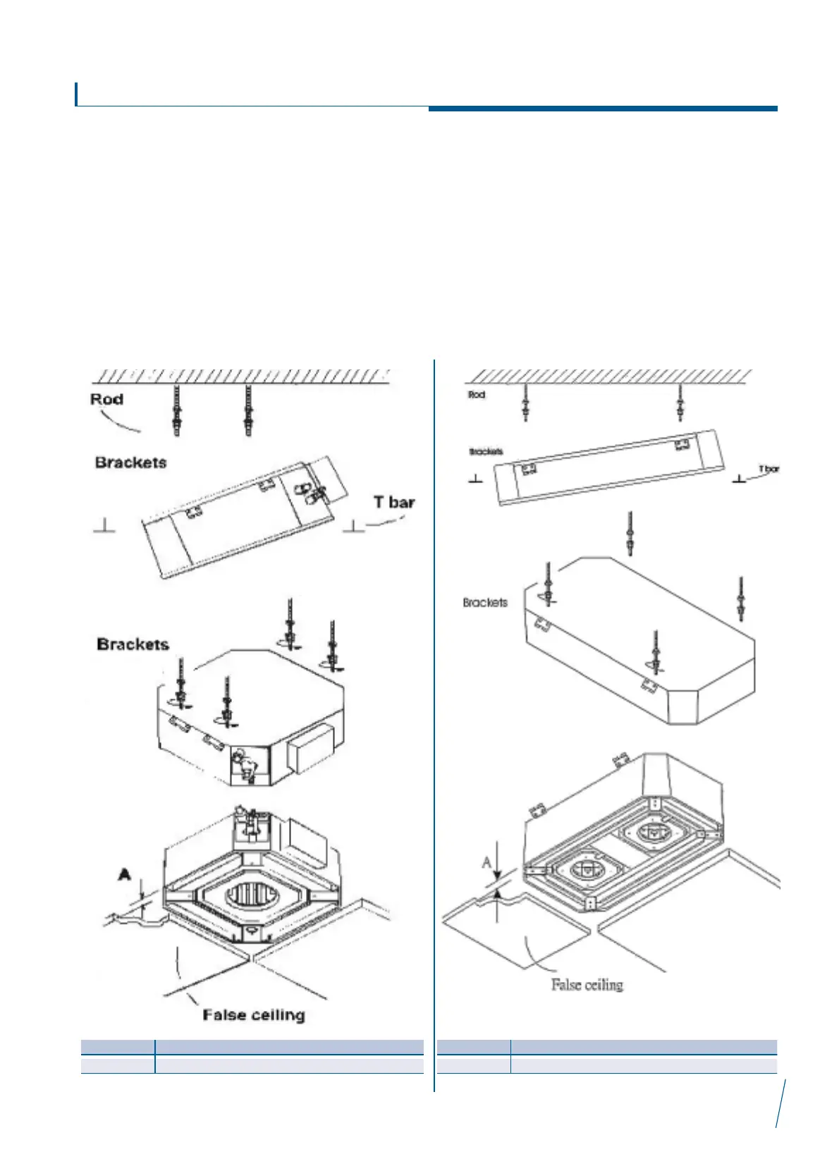
ñ Incline unit (Fig.10, Fig.11, Fig.13, Fig.14) and insert it into
the false ceiling. Insert the rods into the bracket slot.
With minimum height (see table) false ceilings, it might be
necessary to remove some T brackets of the false ceiling
temporarily.
ñ Using a level guide, line up the unit with a spirit level, and
keep dimension between the body and the lower part of the
false ceiling (Fig.12 Fig.15).
ñ Line up the unit to the supporting bars of the false ceiling
tightening the nuts and counter nuts of the threaded rods.
ñ After connection of the condensate drain piping and piping
connections, check again that the unit is level.
Interklima Terminal Units
PCE -VS ñ Hydronic cassette
19
Fig. 10
Fig.12
Fig. 11
Fig. 13
Fig.15
Fig. 14