Interklima Terminal Units
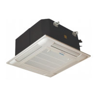
PCE -VS ñ Hydronic cassette
20
ñ The spaces between the unit and ceiling can now be adjusted.
Use the drop rods to make the adjustment.
ñ Check to ensure the unit is level. The drain will then
automatically be lower than the rest of the drip tray.
ñ Tighten the nuts on the suspended rods.
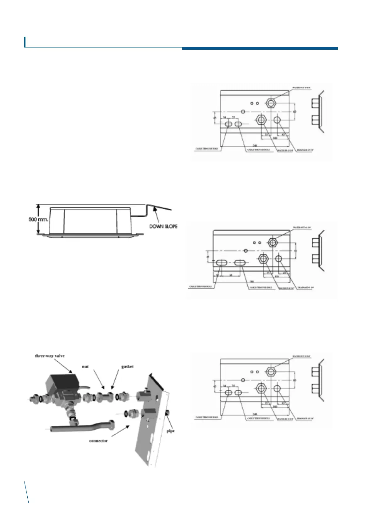
Drain pipe work
Indoor Unit
ñ The unit is fitted with a condensate pump with a 500 mm. lift.
ñ The unit is provided with 22 mm. bore flexible hose 300 mm.
long.
ñ The flexible hose should be fitted into a 22 mm O/S º.
polyvinyl tube and sealed. The drain must be installed with a
downward slope.
ñ On completion the drain line should be insulated
Water connections
ñ Water connections are fixed to the unit body to avoid breaks
when pipes are connected to valve assemblies; it is advisable
to tighten the connection with a spanner.
ñ The upper coil connection is supplied with air purge screw, the
lower connection with water purge screw, suitable for 8mm.
wrench or screw-driver.
ñ Coil is partially drainable; it is advisable to blow air into the coil
for complete drainage.
Pipe connection kit (Option)
Pipe connection dimensional drawings
PCE-03/04-VS
PCE-06/08-VS
PCE-09/10/12/16-VS
Fig.16