4. Terminal block wiring diagram
5.Wiring diagram
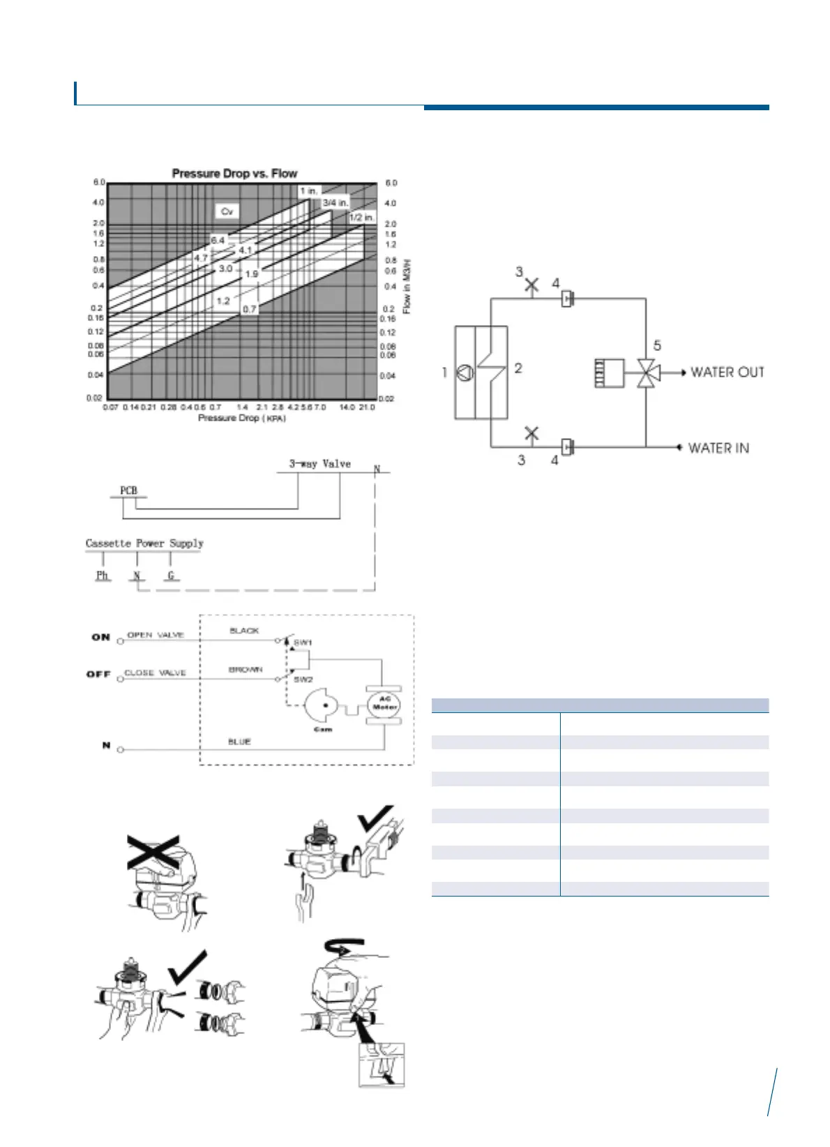
6. Installation
ñ Before installation please read the manual carefully.
ñ Installation must be carried out by qualified personnel
following the instructions in this manual.
ñ The motor must be kept on a horizontal level with the main body.
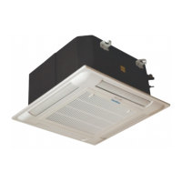
Hydraulic connection diagram
1. FAN 4. JOINT
2. HEAT EXCHANGER 5. SOLENOID
3. AIR VENT
A solenoid valve (optional) must be fitted to cut off water flow.
The choice and installation of components is the responsibility of the
installer who should follow good working practice and legislation in
force in the country concerned.
Particular types of water used for filling or topping up must be treated
with appropriate treatment systems. For references values, see the
table.
Interklima Terminal Units
PCE -VS ñ Hydronic cassette
25
Reference values
pH 6 – 8
Electrical conductivity Less than 200 mV/cm (25
o
C)
Chlorine ions Less than 50 ppm
Sulphuric acid ions Less than 50 ppm
Total iron Less than 0.3 ppm
Alkalinity M Less than 50 ppm
Total hardness Less than 35of
Sulpur ions none
Ammonia ions none
Silicon ions Less than 300 ppm