7
EN
The lter balls in the lter tank ensure that dirt particles and oating
debris are eectively ltered over a long period of time. Dirty water is
drawn from the pool via the suction pipe through the lter pump and
then fed from above into the lter tank. As the water ows through the
lter balls in the lter tank, dirt particles are deposited in the lter balls
and thus ltered out of the pool water. The puried water then ows
through the return pipe back into the pool.
For the operation of the lter system, you need a skimmer (surface
skim mer). Either an integrated skimmer (built into the pool wall) or a
suspended skimmer (attachment to the poolwall).
5. POSITIONING
The installation area you set between the skimmer and the inlet nozzle
so, that there is an adequate safety margin to the pelvic wall. We
recommend putting the lter system in addition on base plates (for
example: washed concrete slabs etc.). These have to be installed with
the spirit level. Under no circumstances you may put your lter system
in a trough or directly into the grass (ood danger or risk of overheating
of the lter pump).
lf you have sunk your pool partially or completely, so it makes sense
to place the lter pump in a lter slot, which should connect directly
to the pelvis. Is your lter pump housed in a lter slot, so it has to be
insured, that the lter slot can’t be slooded. For this purpose you should
bring in a roller-bumishing (crushed rock) in the range of the lter slot,
so that the surrounding- and rainwater can seep away. lt would be
ideal if there is a direct connection to the drain in the sump of the lter
shaft (or sludge pump, with automatic oating switch). Il is important
to ensure that the lter slot should never be airtight, because this may
cause damage, due to condensation water, on the lter pump. The size
of the lter shaft should be selected so that work can be performed on
the lter system.
6. INSTALLATION
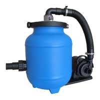
6.1 Assembly of the filter system (illustration 1)
1. Assemble the lter system at the location where the pump nally
will be. The lter pump consists of the following parts:
2. 90° connection bracket
3. Transparent cover
4. Clamping ring
5. Filter tank
6. Screw connection Ø 32/38 mm
7. Bracket for lter pump
8. Filter pump
9. Connection hose Ø 32 mm
6.2 Assembly of the filter system (illustration 2,3,4)
1. Open the clamping ring and remove the transparent cover trom the
lter tank.
2. Fill the lter tank with the lter balls which are included with the
order (approx. 320g).
3. Now place the seal onto the underside of the transparent cover.
Lay the transparent cover once again onto the upper side of the
lter tank. lt is very important to ensure that all surfaces have been
cleaned once again and are free trom any dirt before you do this.
4. The transparent cover is connected to the lter tank using the
clamping ring. The clamping ring is screwed together with the
clamping ring screw and clamping ring screw nut.
5. Fit the connection bracket on the upper side of the transparent cover.
6. Finally, connect the connection bracket with the lter pump. Fasten
all connections with hose clips and ensure that the pump
connecting pieces are adequately sealed using teon tape.
6.3 Pump hose connections (illustration 5)
A: Return line - connection between the lter tank and the connection
to the inlet nozzle (pool). The ltered water is fed back into the pool
at this point.
B: Skimmers - connection between the skimmer connection (pool) and
the lter pump. The water that is going to be cleaned is drawn in
from the pool at this point.
7. FILTER SYSTEM INSTALLATION INSTRUCTIONS
Once the lter system has been properly assembled, the Fiberclean
chamber lled with Fiberclean and the hoses connected as
described above, you may begin with ltration.
Do not plug the system in until advised to do so below.
Make certain the pump is not plugged in to a power supply.
Before operating the lter system, il is important to ensure that the
lter system is positioned outside the pool and is lower than
the pool’s water level. The hose connections must also be correctly
connected and fastened.
lf you haven’t done so already, ll your pool with water. Ensure that
the water level is at least 2,5 - 5 cm above the top of the hose intake
(Skimmer) and return ports in the pool.
The lter system is now vented. lf applicable, open the vent screw
on the upper side of the transparent lter cover until the water ows out
Release the shut o valve at the intake port (Skimmer) in the pool.
lf you plugged the intake port (Skimmer), remove the plug to allow
the water to ow into the intake hose.
With the lter-pump system installed in a location level lower than
your pool’s water level - water will automatically ow into the
pump-lter system.
Allow the lter tank to ll with water.
Check the lter system and the connection hoses for leaks and
resolve, if necessary. Leakage points may possibly arise due to
manufacturing tolerances, which need to be resolved by wrapping
teon tape around the connections before the connection hose is
attached.
Your lter system is now ready for use.
7.1 Cleaning filter balls
The lter balls in the lter tank ensure that dirt particles and oating
debris are eectively ltered over a long period of time.
The lter system will reduce its level of performance in accordance with
the amount of contamination in the water. This must be checked at
regular intervals.
lf you establish that performance levels are decreasing, please follow
one of these two options:
A: Replace the lter balls.
B: Wash the lter balls in a washing machine at a maximum
temperature of 30°C.
7.1 Filtering time
The water in the pool should be circulated and ltered at least 3 to 5
times in a 24 hour period, depending on the load and the size of the
lter system. The time required is based on the performance of the lter
system and the size of the swimming pool. However, we recommend a
minimum running time of 12 hours per day.
8.POWER SOURCE INSTRUCTIONS
8.1 Technical data
Circulation power 2,800 1/h
Pump is not self-priming
» Maximum water temperature 35 °C
230V/100W
Tank Ø 200 mm
Connector Ø 32/38 mm
Ground plate
 Loading...