2 / 10 P/N 466-1452 • REV E • ISS 16OCT18
Receiver operation
This section covers receiver operation functions including the
DIP switch, tamper switch, advance (ADV) and select (SEL)
switches, outputs, and LEDs.
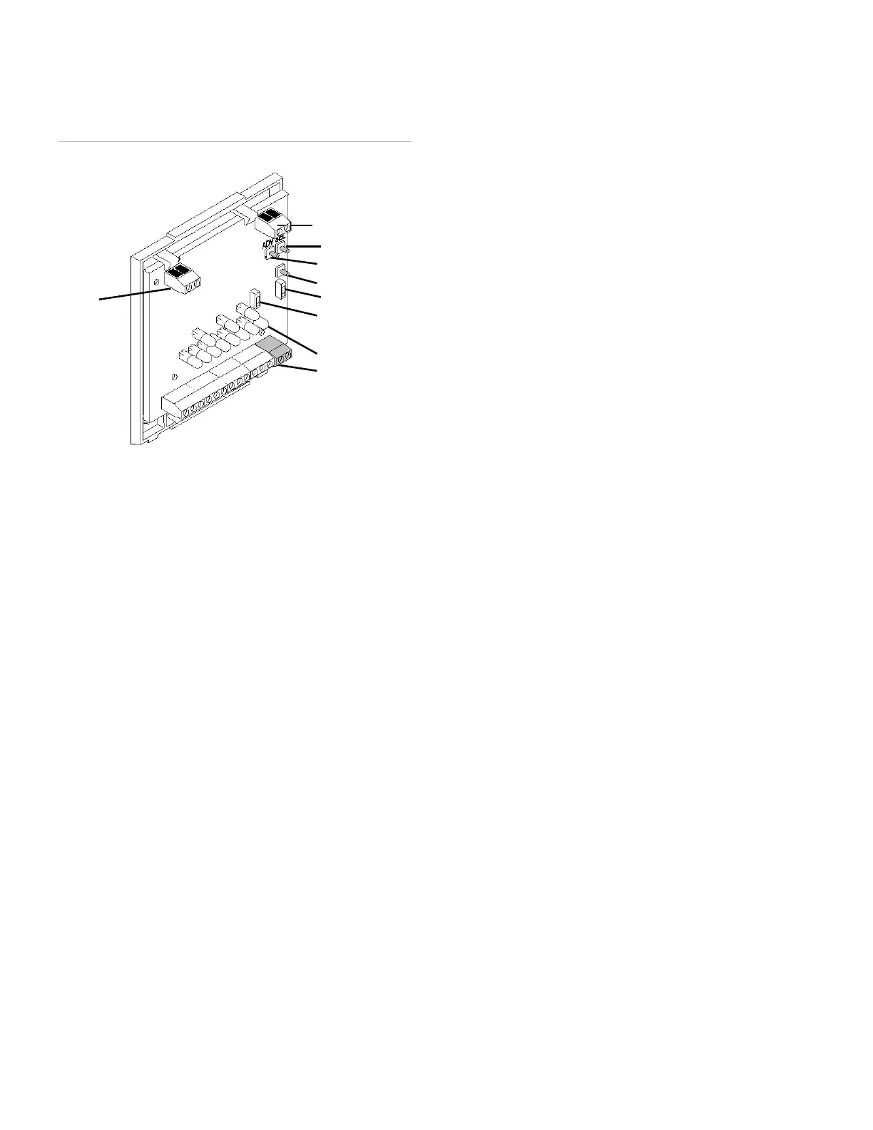
Figure 2: Receiver components
Program Mode Dip Switch
Program mode dip switch on the receiver board (Figure 2:
Receiver components) controls the mode of operation. When
the DIP switch is up, the receiver is in program mode. When
the DIP switch is down, the receiver is in run mode.
Supervisory Dip Switch
Supervisory dip switch (see Figure 2) controls if the RF
supervisory is 1 or 4 hours. On 1 hour, Off 4 hours
Tamper switch
The tamper switch functions in two ways, depending on
which setting the DIP switch is on (program mode or run
mode).
In program mode
When the receiver is in program mode, if you press the
tamper switch you will cycle through the three programming
areas:
• Learn/delete transmitters.
• Configure zone/trouble outputs N/O or N/C.
• Enable/disable zone supervision, or keychain
momentary or maintained output.
In run mode
If no transmitters are learned into zone 8, the receiver tamper
switch is active. If you trip the tamper switch (by removing
the cover) or remove the antenna you will cause a tamper
alarm on zone 8.
If one or more transmitters are learned into zone 8, the
tamper feature is inactive and does not cause an alarm.
ADV and SEL switches
You can only use these switches when you are in program
mode. The ADV (advance) switch lets you cycle to the zone
you want to program. The SEL (select) switch lets you select
the zone or trouble output for programming.
Outputs
The receiver uses open-collector transistors for the zone and
trouble outputs (see Figure 2). The outputs can be open
(high impedance) or closed (shorted to ground), which can
be configured to be normally closed (N/C) or normally open
(N/O). Each output can be wired to the control panel.
Zone outputs
There are eight zone outputs labeled 1 through 8. When a
learned transmitter is activated, the corresponding zone
output switches to the alarm state and remains in alarm for at
least three seconds, until the transmitter is restored to its
non-alarm state. If the control panel connected to the
receiver is armed, the panel activates an alarm in response
to the zone output transition.
Zone 7 - Receiver jam detect
If no transmitters are learned into zone 7, this output trips
whenever the receiver detects a jam condition. Receiver
jamming occurs when the receiver detects a constant signal
for 30 seconds. The receiver jam detect feature is disabled
automatically if transmitters are learned into zone 7.
Zone 8 - Receiver cover/antenna tamper and sensor
tamper summary
If no transmitters are learned into zone 8, this output trips
whenever the receiver cover or the antenna is removed, or
when the tamper switch of any learned transmitter in any
zone is tripped. When transmitters are learned into zone 8,
the receiver cover/antenna tamper and sensor tamper
summary features are disabled.
Trouble outputs
There are two trouble outputs labeled B (low battery
summary) and S (supervisory failure summary).
B - Low battery
When a learned transmitter sends a low battery signal, this
output switches to, and remain in the alarm state until the
receiver receives a signal from the same transmitter with a
good battery.
Antenna terminal
block
Select switch
Advance switch
Tamper switch
Program Dip switch
Supervisory Dip
switch
LEDs
Receiver terminal
strip
 Loading...