EasyManua.ls Logo

Intermatic IG2200 - User Manual

Intermatic IG2200
2 pages
Print Icon
To Next Page IconTo Next Page
Loading...
IMPORTANT SAFETY INSTRUCTIONS • SAVE THESE INSTRUCTIONS
INSTALLATION INSTRUCTIONS
IG2200 CONSUMABLE SURGE SERIES
TYPE 2 SURGE PROTECTIVE DEVICES
APPLICATION NOTES
1. Thoroughly read instructions before installing SPD unit.
2. This product is designed to protect against momentary transient overvoltage events.
3. This product does not protect against nearby lightning strikes.
4. This device features internal protection that will disconnect the surge protective component at the end of its useful life but will maintain power to the load-now unprotected. If this situation is undesirable
for the application, follow the manufacturers instructions for replacing SPD module(s).
5. Observe warnings and instructions on front panel and unit label of product.
DEFINITIONS
Type 2 SPD: A typical type 2 SPD installation will be connected to the load side of the service panel and is intended to be installed with overcurrent protection to the SPD.
INSTALLATION:
1. Verify system voltage.
2. Make sure SPD is correctly rated for system.
3. Determine mounting location of SPD unit.
The SPD unit should be located as close as possible to the load to be protected.
4. Mount enclosure
- Remove dead front from SPD unit.
- Disconnect power to SPD unit at power source before installation.
- Remove needed knockout from SPD unit once wire routing has been determined.
- Only one conduit connection may be made to the SPD enclosure.
- Mount enclosure using suitable fasteners in locations shown below. Do not rely on conduit fitting to support SPD unit.
5. Follow wiring diagram for all connections. (located within instruction sheets and SPD unit).
- Cut all wires to a minimum suitable length while maintaining a 4” recommended bend radius.
- Do not coil excess wire.
- Make sure all connections are secure.
- Replace dead front.
6. Energize SPD unit
- Flip circuit breaker to ON position at service panel or disconnect switch(es).
- Indicators: Each Consumable Surge Module has a blue LED to indicate the SPD unit has
power and a green LED to indicate that the SPD module is providing protection.
To be installed or serviced only by qualified personnel.
Disconnect power at the service panel or disconnect switch(es) before installing or servicing.
Installation and wiring must be in accordance with national and local electrical code requirements.
Confirm consumable Surge Protective Device (SPD) is rated for the correct voltage and current for your application.
KEEP DOOR CLOSED AT ALL TIMES when not servicing.
Bonding between conduit connection and enclosure is not automatic and must be provided as part of the installation. Only one connection may be made to SPD enclosure.
For outdoor locations, raintight, or wet locations, conduit hubs that comply with requirements of the UL514B (standard for fitting for conduit and outlet boxes) are to be used.
Risk of Fire or Electric Shock
WARNING
8 1/2"
3 1/4"
1 5/8"
5 3/4"
5"
2 1/2"
2 1/2"
5"
1 5/8"
3/4" 3/4"
1 5/8"
10 3/8"
Plastic outdoor enclosure Metal indoor enclosure
(Flush mount kit IG2200--FMK)
Metal outdoor enclosure
Blue LED: Power indicator
Green LED: Status indicator
Alignment key of module
ON: Protection is being provided.
OFF: Module is no longer providing
protection. Replace module as soon
as possible.
Consumable Surge
Module
SPD
UNIT
Main Breaker
2-Pole, 30A circuit
breaker
Green (Ground)
Type 2 Installation
SERVICING INSTRUCTIONS:
The Consumable SPD Module will absorb the energy of the surges to protect the connected load. If the green LED is OFF, the SPD module is no longer providing protection and should be replaced as soon
as possible.
TO REPLACE CONSUMABLE SURGE MODULE:
1. POWER MUST BE REMOVED FROM THE MODULE BEFORE REPLACING.
2. Disconnect power to SPD unit at service panel and/or disconnect switch(es) before servicing.
3. Remove module to be replaced by firmly pulling straight out from SPD unit. The module door within the unit will close once the module is removed.
4. Make sure SPD module is correctly rated for system.
5. Place new module back into SPD unit. Make sure SPD module alignment key is oriented correctly when inserting.
6. Make sure the module is fully seated.
7. Re-energize SPD unit.
8. Verify the blue and green LED’s within each module are lit.
Black (Line)
Black (Line)
Neutral (White)
*C/B
GND (green)
Neutral (white)
Line (black)
Line (black)
SPD TYPE 2 WIRING DIAGRAM
120/240 VAC SINGLE PHASE
SPD
*2 Pole 30 amp circuit breaker in Service Panel.
Question and Answer IconNeed help?

Do you have a question about the Intermatic IG2200 and is the answer not in the manual?

Summary

Important Safety Instructions

Risk of Fire or Electric Shock

Crucial warnings regarding fire or electric shock hazards during installation and servicing.

Qualified Personnel Installation

Ensures installation and servicing are performed only by qualified individuals.

Power Disconnection Before Servicing

Mandates power disconnection at the source before any installation or servicing.

Adherence to Electrical Codes

Installation and wiring must comply with all national and local electrical codes.

Installation Guide

Follow Wiring Diagram

Connect wiring according to the provided diagram, ensuring minimum wire length and secure connections.

Servicing Instructions

Module Replacement Procedure

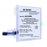
Steps for replacing the consumable surge module, including safety precautions and verification.

Overview

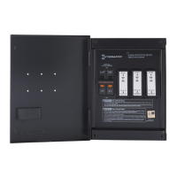
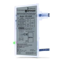
The Intermatic IG2200 Consumable Surge Series is a Type 2 Surge Protective Device (SPD) designed to safeguard connected electrical equipment from momentary transient overvoltage events. It is intended for installation on the load side of the service panel and requires overcurrent protection.

Function Description:

The primary function of the IG2200 SPD is to absorb the energy of voltage surges, thereby protecting downstream electrical loads. It features internal protection that disconnects the surge protective component at the end of its useful life while maintaining power to the load. This means that even after the surge protection capability is exhausted, the device will not interrupt the power supply to the connected equipment, though the equipment will then be unprotected from future surges. It is crucial for users to be aware of this and replace the SPD module promptly when its protective function is no longer active. The device is specifically designed to handle over-voltage events resulting from momentary voltage spikes or surges on an AC power line, preventing them from affecting downstream equipment. It is important to note that this device does not protect against nearby lightning strikes or provide protection during utility voltage swells or loss of neutral conditions, as these are not considered transient events. The IG2200 is suitable for both residential and commercial applications.

Usage Features:

The IG2200 SPD is designed for straightforward installation and monitoring.

  • Installation: The device should be installed by qualified personnel in accordance with national and local electrical code requirements. Before installation or servicing, power must be disconnected at the service panel or disconnect switch. The SPD unit should be located as close as possible to the load it is intended to protect. The enclosure can be mounted using suitable fasteners, and only one conduit connection should be made to the SPD enclosure. For outdoor or wet locations, raintight conduit hubs complying with UL514B standards must be used. Wiring connections must follow the provided diagram, ensuring all wires are cut to a minimum suitable length with a 4-inch recommended bend radius, avoiding excess coiling, and making sure all connections are secure.
  • Status Indicators: Each Consumable Surge Module within the SPD unit is equipped with two LED indicators:
    • A blue LED indicates that the SPD unit has power.
    • A green LED indicates that the SPD module is actively providing protection. When the green LED is OFF, it signifies that the module is no longer providing protection and needs to be replaced.
  • Enclosure Options: The IG2200 offers various enclosure types, including plastic outdoor, metal outdoor, and a metal indoor enclosure (flush mount kit).
  • Voltage Rating: Users must confirm that the SPD is correctly rated for their system voltage (e.g., 120/240 VAC single phase).

Maintenance Features:

The IG2200 Consumable Surge Series is designed with user-replaceable modules to ensure continuous protection.

  • Module Replacement: The Consumable SPD Module is designed to absorb surge energy. When its green LED is OFF, it indicates that the module is no longer providing protection and should be replaced as soon as possible. The replacement process is critical and must be performed safely:
    1. Power Disconnection: Power must be removed from the module before replacement. This involves disconnecting power to the SPD unit at the service panel and/or disconnect switch(es).
    2. Module Removal: The module to be replaced is removed by firmly pulling it straight out from the SPD unit. The module door within the unit will automatically close once the module is removed.
    3. New Module Insertion: Ensure the new SPD module is correctly rated for the system. Place the new module back into the SPD unit, making sure its alignment key is correctly oriented when inserting and that the module is fully seated.
    4. Re-energization and Verification: After replacing the module, re-energize the SPD unit. Verify that both the blue and green LEDs within each module are lit, confirming power and active protection.
  • Warranty: The product comes with a limited warranty, covering defects in material and workmanship for the base units and consumable modules. It also includes a connected equipment warranty, offering repair or reimbursement for major household connected electrical equipment damaged as a direct result of the SPD's failure to protect against power transients. Claims must be submitted promptly, following a specific procedure that includes contacting the Intermatic Claims Center, obtaining an Incident Claim Report, filing a claim with homeowners insurance, and sending the device and required documentation to Intermatic.

Intermatic IG2200 Specifications

General IconGeneral
TypeWhole House Surge Protector
Voltage Rating120/240V AC
Response Time<1 nanosecond
EnclosureNEMA 3R
UL RatingUL1449 3rd Edition
Maximum Surge Current50kA
Warranty5 years
Protection ModesL-N, N-G
Indicator LightsLED status indicators

Related product manuals