Main Breaker
2-Pole, 20 A circuit
breaker shown
A=Black (Line)
B=Black (Line)
C=Neutral (White)
D=Green (Ground)
Line
Line
Neutral
Ground
GREEN
WHITE
BLACK
BLACK
120 V
120 V
120 V
240 V
120 V
Figure 1
Type 1 Installation
Figure 2
Type 2 Installation
Type 1 installation:
A typical installation of a type 1 SPD will be connected between the secondary of the service transformer and the line side of the service
panel. This installation is intended to be installed without overcurrent protection to the SPD.
1. Determine location:
• Ensure conductor lengths are as short and straight as possible for best performance. Do not coil excess wire. The SPD functions
best if all bends in wires are rounded, ideally to a 4” radius. Hard 90 degree bend will reduce efficiency. Cut all leads to the correct
length. Do not coil excess leads.
• Install appropriate weatherproof fittings if the unit is to be mounted outside.
2. Connect wires as shown in figure 1.
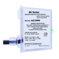
3. Ensure all mounting and connections are correct and secure. Once energized the green indicator LED will be ON and visible through
the cover of the SPD.
Type 2 installation:
A typical installation of a type 2 SPD will be connected to the load side of the service panel and is intended to be installed with overcurrent
protection to the SPD.
1. Determining location:
• Ensure conductor lengths are as short and straight as possible for best performance. Do not coil excess wire. The SPD functions
best if all bends in wires are rounded, ideally to a 4” radius. Hard 90 degree bend will reduce efficiency. Cut all leads to the correct
length. Do not coil excess leads.
• Install appropriate weatherproof fittings if the unit is to be mounted outside.
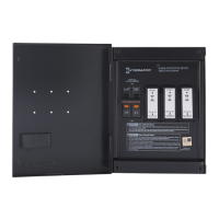
• IG3240FMP33 is also available for flush mount applications.
2. Connect the green wire from the SPD to the ground bus in the panel.
• Connection may also be made to the neutral/ground bus bar if panel does not have a separate ground bus bar.
3. Connect the white wire from the SPD to the neutral bus bar in the panel as shown in figure 2.
4. Connect the two black wires to a circuit breaker as shown in figure 2. For best performance from SPD the maximum recommended
circuit breaker size of 240 V, 20 A, 2-pole should be used.
5. Ensure all mounting and electrical connections are correct and securely fastened. Once energized the green indicator LED will be ON
and visible through the cover of the SPD.
Maintenance:
• AC Voltage SPD:
• Periodically check SPD to ensure green indicator LED is ON. If green LED is OFF, protection has diminished and the SPD should be
replaced immediately.
INSTALLATION INSTRUCTIONS
IMPORTANT SAFETY INSTRUCTIONS • SAVE THESE INSTRUCTIONS
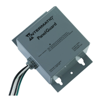
Model IG3240RC3
Type 1 or Type 2 Surge Protection Device (SPD)
• For Indoor /Outdoor use.
• Disconnect power at the circuit breaker(s) or disconnect switch(es) before installing or servicing.
• Installation and/or wiring must be in accordance with national and local electrical code requirements.
• Installation and service to be performed by a qualied licensed technician or electrician.
• Suitable for use on a circuit capable of delivering not more than 50,000 rms symmetrical amperes.
• For outdoor locations or wet locations (rain-tight), conduit hubs that comply with requirements of the UL514B (standard for tting
conduit and outlet boxes) are to be used..
• KEEP DOOR CLOSED AT ALL TIMES when not servicing.
WARNING
Risk of Fire or Electric Shock
NOTICE
• This unit contains no serviceable parts.
• This product does not protect against direct lightning strikes.
Page 1