Page 10
GENERAL PUMP
A member of the Interpump Group
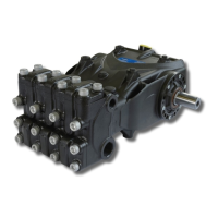
EV SERIES
Determining the shim pack:
Perform the operation while the piston/con-rod guide units are assembled, the con-rod caps are disconnected
and the con-rods are pushed downwards. Insert the pump shaft without tab into the casing, making sure the
PTO shaft comes out of the correct side.
Secure the PTO side flange to the casing, taking care with the lip seal as described previously and tighten
the fixing screws to the recommended torque.
Then feed the flange on the indicator side without shims in the crankcase and start to move it closer, manual-
ly screwing the M6x40 service screws in equally, with small rotations such as to move the cover in slowly and
correctly.
At the same time, check that the shaft rotates freely by turning it manually.
Continuing the procedure in this way, a sudden increase in hardness during shaft rotation will soon be experi-
enced.
At this point, halt the forward movement of the cover and loosen the fixing screws completely.
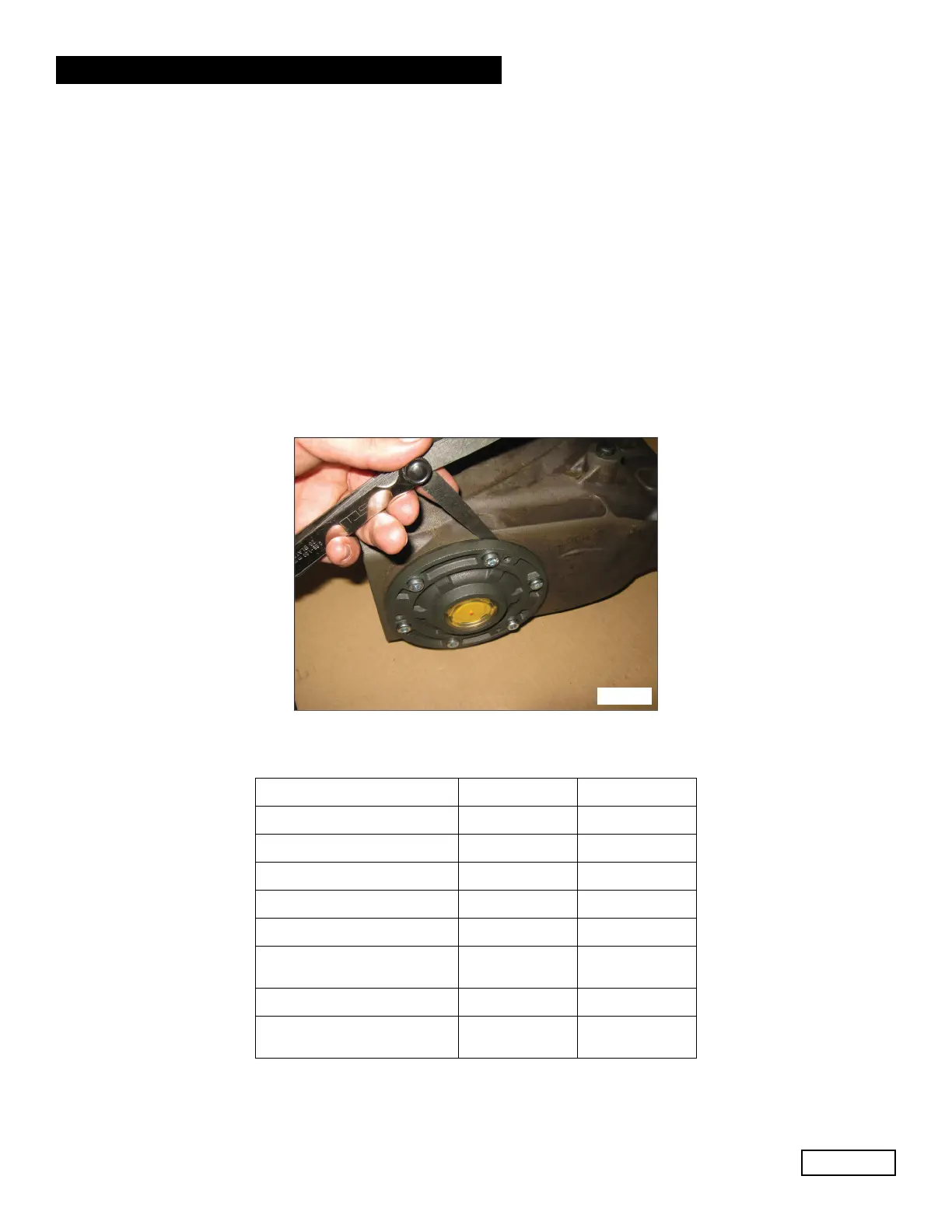
With the aid of a feeler gauge, measure the clearance between the side cover and pump casing (Fig. 14).
Fig. 14
Proceed to determine the shim pack, using the table below:
Detected Measurement Shim type No. of Pieces
From: 0.05 - 0.10 / /
From: 0.11 - 0.20 0.1 1
From: 0.21 - 0.30 0.1 2
From: 0.31 - 0.35 0.25 1
From: 0.36 - 0.45 0.35 1
From: 0.46 - 0.55
0.35
0.10
1
1
From: 0.56 - 0.60 0.25 2
From: 0.61 - 0.70
0.35
0.25
1
1
Ref 301038 Rev. A
07-20