GENERAL PUMP
A member of the Interpump Group
Page 14
EV SERIES
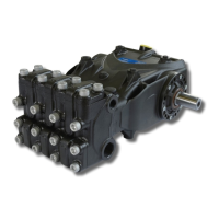
Insert the suction and outlet valve units, checking that they are fully inserted in the head
seat.
Then apply the valve covers and calibrate the respective M12x130 + M12x45 screws (Inlet
valve cover) and M12x35 (outlet valve cover) screws, for the values of the torques and tight-
ening sequences follow the instructions in chapter 3.
Fig. 23
2.2.3 Disassembly of The Head-Seals
Replacement of the seals is necessary from the moment you begin to detect water leaks from the drain-
age holes provided on the back of the pump casing, and at the intervals indicated in the “PREVENTIVE
MAINTENANCE” table in chapter 11 of the Owner’s Manual.
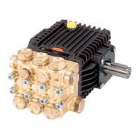
A) Unscrew the M12x130 head fixing screws as indicated in (Fig. 24).
B) Separate the head from the pump casing.
C) Extract the high pressure seals from the head and the low pressure ones from the support, using
simple tools as indicated in (Fig. 25), being careful not to damage the respective housings.
Fig. 24
Ref 301038 Rev. A
07-20