GENERAL PUMP
A member of the Interpump Group
Page 11
EV SERIES
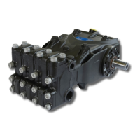
Fig. 15
Once the type and number of shims have been determined using the table, check the following: assemble the
shim pack on the indicator side cover centering (Fig. 15), secure the cover to the casing, following the
procedure in par. 2.1.2, and tighten the screws to their recommended torque.
Check that the shaft rotation stall torque is between 2.95 ft lbs. and 4.43 ft lbs. (4 Nm and 6 Nm).
If this torque is correct, connect the con-rods to the bend shaft and to the next stages. If it is not, redefine the
shim pack, repeating the operations.
2.2 Repairing Hydraulic Parts
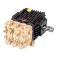
2.2.1 Disassembly of The Head Valve Units
Operations are limited to inspection or replacement of valves, if necessary and, however, at the intervals indi-
cated in the “PREVENTIVE MAINTENANCE” table in chapter 11 of the Owner’s Manual.
The valve units are assembled inside the head.
Operate as follows to extract them:
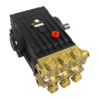
- Unscrew the 4 M12x130 and 4 M12x45 suction valve cover fixing screws and the 8 M12x35 outlet
valve cover fixing screws (Fig. 16 and Fig. 17);
- Extract the suction and outlet valve units using an extractor hammer code 26019400
(Fig. 18).
Fig. 16 Fig. 17
Ref 301038 Rev. A
07-20