264
PO
S AVE THESE INSTRUCTIONS
(264PO) SPA (JET + BUBBLE) ENGLISH 7.5” X 10.3” PANTONE 295U 05/10/2017
English
Page 11
SET UP (continued)
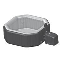
Spa Control Unit Installation
1.
Connect the spa control unit to the spa tub
(see drawing 9)
. Hand-tighten the connectors securely.
Do not use tools to tighten.
CAUTION:
Do not sit, lean, cover or place any objects over the spa control unit.
2.
Attach the two fi lter cartridge housing assemblies to the two outlet grids on the inside of the spa (marked
“B”). Infl ate the spa tub fi rst before installing fi lter pump fi ttings.
ATTENTION!
In order to comply with the requirements of the Virginia Grahame Baker Act, suction
outlets cannot be covered while the spa is in use. The Act was intended to address high suction/
volume circulation systems but does not exclude low volume systems as used on this spa. Accordingly,
remove the fi lter cartridge assemblies and any other spa cleaning attachment from the spa outlets
before spa usage
(see drawing 10)
. Re-attach them after usage for water fi ltration and cleaning.
3.
Before fi lling with water ensure the bottom drain valve caps are securely closed on the inside and
outside.
4.
Fill the spa tub with freshwater to a level between MIN and MAX marked on the inside of the spa wall.
Do not over fi ll the spa. Never move the spa tub with water inside and/or with the control base attached
to the spa as the spa or control base may be damaged.
WARNING:
Never pour water with a temperature higher than 104°F (40°C) into the spa directly. It is
recommended to fi ll the spa tub with lukewarm water for quick heating and energy saving.
5.
Place the spa cover and spa air bladder (pre-installed in spa cover) over the spa tub, and make sure the
spa cover buckles are locked using the key provided after pulling the buckled straps tight.
IMPORTANT:
Inspect the spa cover regularly for leak, premature wear and tear or deterioration. Never
use a damaged spa cover.
6.
Ensure the spa is plugged into a grounded electrical socket and press the button to turn on the
control unit panel buttons fi rst. Press the button on the control panel to activate the heater, see “Spa
Control Unit Panel” operation section.
IMPORTANT:
The following conditions will lead to slow water heating:
• The ambient temperature is lower than 50ºF (10ºC).
• Outdoor wind speed is above 8-12 mph (3.5-5.4 m/s).
• The jet function is activated when heating the spa water.
• The spa is not properly covered with the spa cover when the water is heating.
10
B
B
C
A
A
C
B
9
Defl ation
For Spa Tub Wall:
1.
Unscrew the cap to reveal the stem, push the stem
in and turn 90 degree right to secure it in the down
position
(see drawing 8)
.
2.
Once the defl ation is completed, push the stem in
and turn 90 degree left to return it to the infl ation
position.
3.
Replace the cap back.
For Cover Air Bladder:
1.
Pull valve cap out and squeeze the valve at its base until defl ated.
2.
Close and recess the valve back.
8
 Loading...