8
Zusammenbau von Ach-
sen und Bodenplatte
• Verbinden Sie die Achsen
(Abb. 05) mit der Boden-
platte (Abb. 08, A-E)
• Achten Sie bei der Verbin-
dung der Achsen auf die
richtige Richtung
Installation of base plate
and shafts
• Insert the shafts (g. 05)
into the base plate (g.
08, A-E)
• Please note the correct
direction of rotation
Zusammenbau von Ach-
sen und Armen (Teil 1)
• Platzieren Sie nun die Arme
auf den Achsen, wie in
Abb. 05 dargestellt.
Der Maßstab der Abbildung
ist 1:1
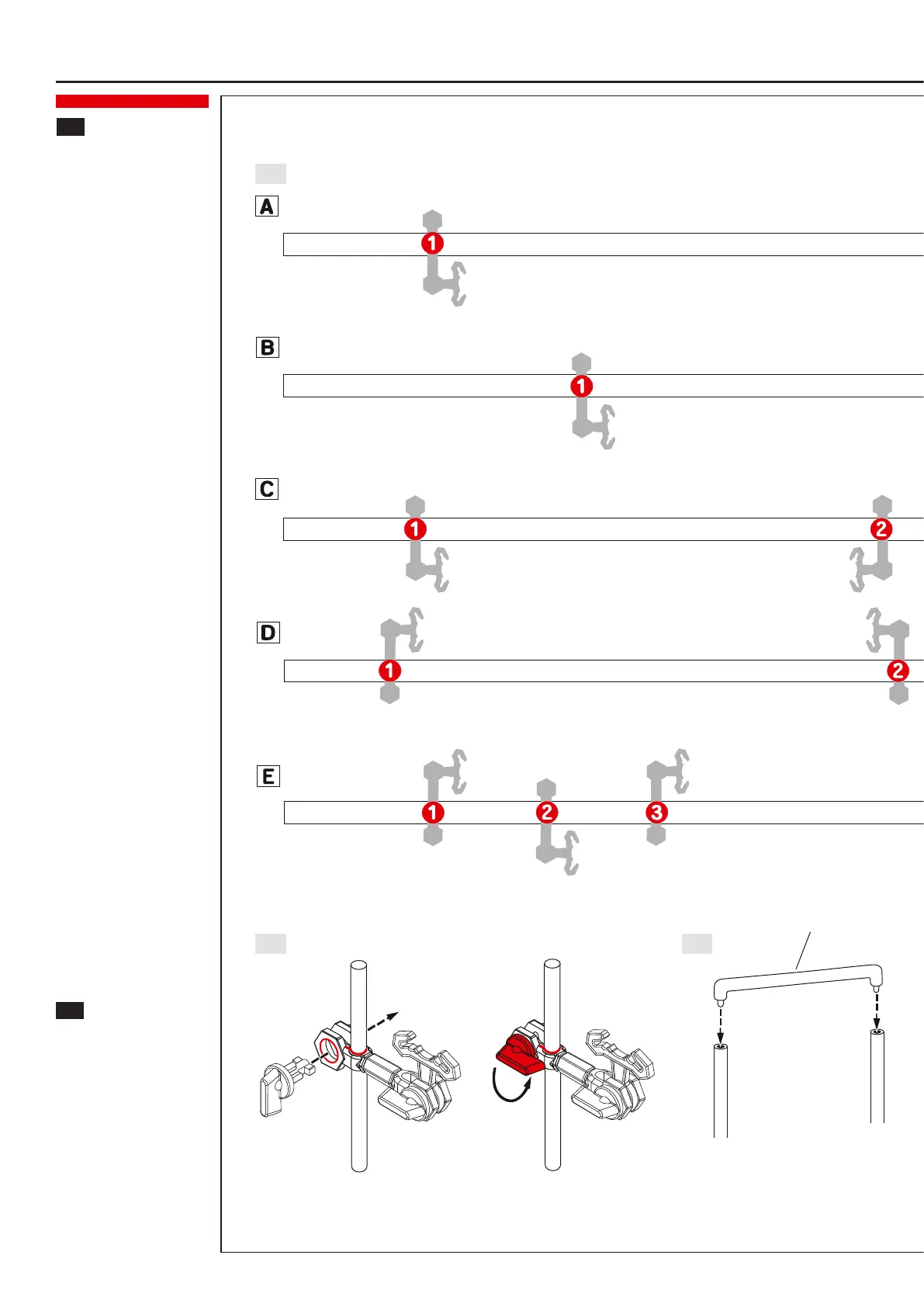
• Positionen der Arme
(Abb. 05): Die Achsen
werden im Maßstab 1:1
dargestellt. Platzieren Sie
die Arme exakt an den mit
den roten Punkten markier-
ten Positionen. Beachten
Sie dabei Reihenfolge und
Richtung der Arme
• Armhalter B auf die Achsen
schieben. Arretierung in
Armhalter B stecken und
um 90° drehen, um den
Arm zu xieren (Abb. 06)
Hinweis: Um den Armwin-
kel zu verändern, muss
vorher die Fixierung wieder
gelöst werden.
• Verbinden Sie die Achsen
mit den Verbindungsstück
[S3] (Abb. 07)
• Beachten Sie die richtigen
Positionen der Achsen in
der Bodenplatte (Abb. 08
+ Abb. 12)
Installation of shafts and
arms (part 1)
• Attach the arm to the shaft
(picture shows a scale of
1:1)
• Positions of arms (g. 05):
Shafts are shown in a scale
of 1:1. Attach the arms
to the exact pre-dened
red positions. Please note
the correct order and
directions of arms
• Insert the shaft into arm
holder B. Insert the arm
wrench into the arm holder
B and turn it by 90 degrees
to x the arm (g. 06)
Note: To modify the angle
of the arm, release the
xation rst
• Attach the connecting
pieces [S3] to the shafts
(g. 07)
• Please note the exact pre-
dened positions of the
shafts on the base plate
(g. 08 + g. 12)
[S3] Verbindungsstück
[S3] Connecting piece
Hinweis: Beim Drehen der Arretierung darauf achten, dass der Arm in der gewünschten Position bleibt.
Note: When turning the arm wrench, make sure not to change the right position of the arm.
Montage von Achsen, Armen und Bodenplatte
05
06 07
4
5
 Loading...