93
Matrix Mono
Part 3 - Installaon and Field Sengs
Matrix Mono
92
Inventor Matrix Mono Engineering Data Book
Figure 3-7.43: Preheating for floor screens
7.15.3 FLOOR DRYING UP
MENU > FOR SERVICEMAN > SPECIAL FUNCTION > FLOOR
DRYING UP
For newly-installed under-floor heating systems, floor drying
up mode can be used to remove moisture from the floor slab
and subfloor to prevent warping or rupture of the floor during
floor heating operation. There are three phases to the floor
drying up operation:
Phase 1: gradual temperature increase from a starting point of 25°C to the peak temperature
Phase 2: maintain peak temperature
Phase 3: gradual temperature decrease from the peak temperature to 45°C
t_DRYUP sets the duration of Phase 1.
t_HIGHPEAK sets the duration of Phase 2.
t_DRYDOWN is the duration of Phase 3.
T_DRYPEAK sets the heat pump’s leaving water set temperature for Phase 2.
START TIME sets the floor drying up operation start time.
START DATE sets the floor drying up operation start date.
The heat pump’s leaving water set temperature during the floor drying up operation is illustrated in Figure 3-7.40.
During the floor drying up operation all buttons except OK are inactivated. To exit
the floor drying up operation, press OK and then select YES when prompted.
Note: In the event of a heat pump malfunction, floor drying up mode will continue if
a backup electric heater and/or additional heating source is available and configured
to support space heating mode.
12.1 PREHEATING FOR FLOOR
Preheat for floor is
running for 25 minutes.
Water flow temperature is 20°C.
OK CONFIRM
12.1 PREHEATING FOR FLOOR
Do you want to turn off the preheating
for floor function?
OK CONFIRM
NO YES
Figure 3-7.44: FLOOR DRYING UP menu
Figure 3-7.45: FLOOR DRYING UP settings
Figure 3-7.46: FLOOR DRYING UP screen
12.2 FLOOR DRYING UP
8 days
5 days
5 days
45°C
15:00
ADJUST
t_DRYUP
t_HIGHPEAK
t_DRYDOWN
T_DRYPEAK
START TIME
12.2 FLOOR DRYING UP
01-01-2019
ADJUST
START DAY
ENTER EXIT
12.2 FLOOR DRYING UP
01-01-2019
ADJUST
START DAY
ENTER EXIT
Matrix Mono
93
Part 3 - Installation and Field Settings
7.16 AUTO RESTART
MENU > FOR SERVICEMAN > AUTO RESTART
AUTO RESTART sets whether or not the unit re-applies the user interface settings
when the power returns following a power failure. Select YES to enable auto restart or
NON to disable auto restart.
If the auto restart function is enabled, when the power returns following a power
failure, the unit re-applies the user interface settings from before the power failure. If
the auto restart function is disabled, when the power returns after a power failure,
the unit won’t auto restart.
7.17 POWER INPUT LIMITATION
MENU > FOR SERVICEMAN > POWER INPUT LIMITATION
POWER INPUT LIMITATION sets the type of
power input limitation and the
setting range is 0-8. If the unit will operate at larger power input, 0 should be
selected. If the unit will operate at a lower power input, 1-8 should be selected
and the power input and capacity will decrease.
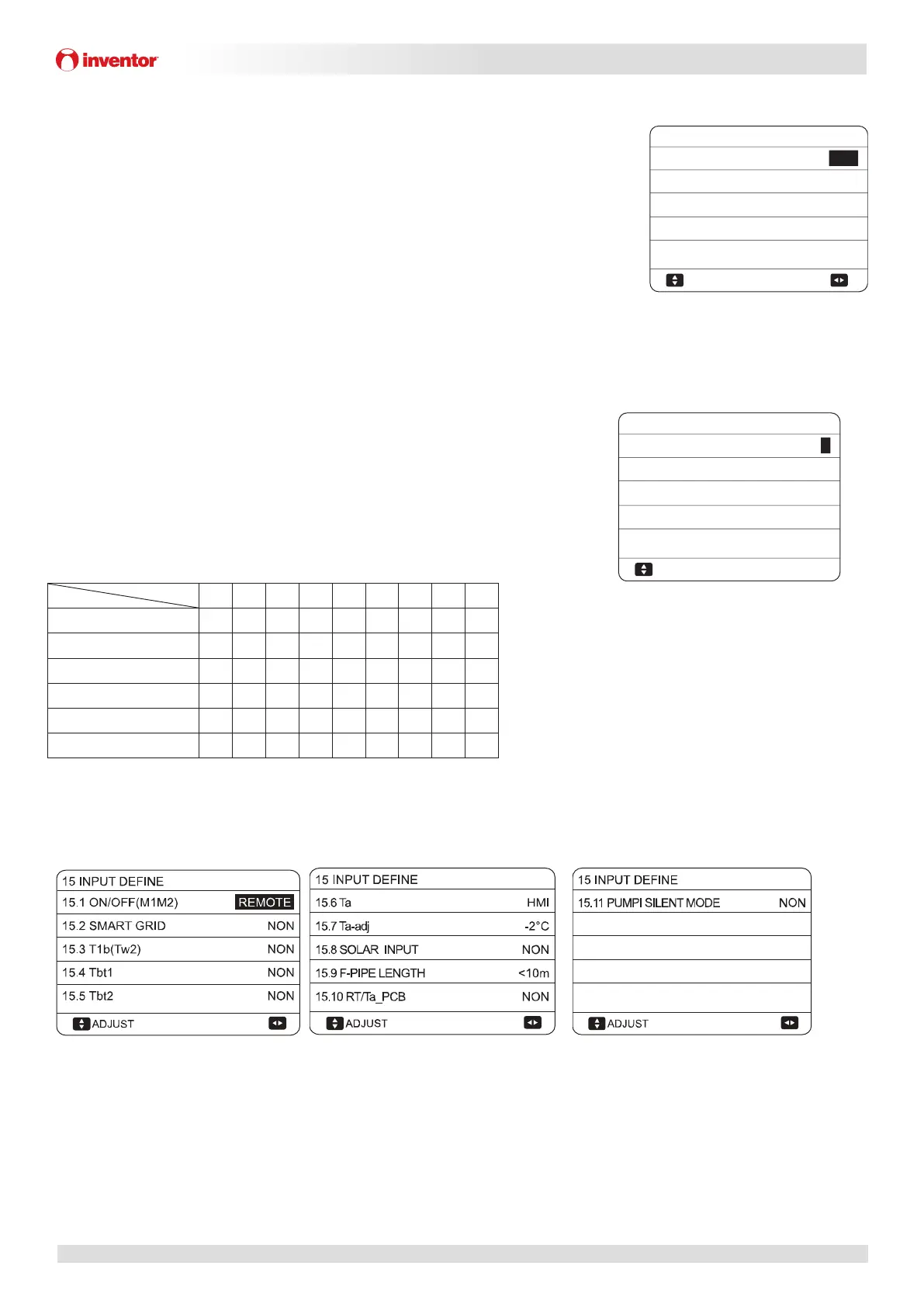
Model No. 0 1 2 3 4 5 6 7 8
4/6kW 18 18 16 15 14 13 12 12 12
8/10kW 19 19 18 16 14 12 12 12 12
12/14kW(1N) 30 30 28 26 24 22 20 18 16
16kW(1N) 30 30 29 27 25 23 21 19 17
12/14kW(3N) 14 14 13 12 11 10 9 9 9
16kW(3N) 14 14 13 12 11 10 9 9 9
7.18 INPUT DEFINE
MENU > FOR SERVICEMAN > INPUT DEFINE
Figure 3-7.50: INPUT DEFINE
INPUT DEFINE sets sensors and functions to fulfill with installation.
ON/OFF(M1M2) sets the control function of M1M2 for remote ON/OFF of unit or AHS or TBH
SMART GRID sets whether SMART GRID control signal is connected to hydronic PCB.
T1b(Tw2) sets whether T1b sensor exist in the installation.
Tbt1 set whether balance tank temperature sensors are installed in the balance tank. (Tbt1 sensor, individually purchase;Tbt2,
reserved)
Ta sets the Ta sensor connection type (HMI: Ta on wired controller; IDU: Ta connected on hydronic PCB)
Figure 3-7.47: AUTO RESTART menu
Figure 3-7.48: POWER INPUT LIMITATION menu
Figure 3-7.49: Limitation value (unit:A)
13 AUTO RESTART
YES
NON
ADJUST
13.1 COOL/HEAT MODE
13.2 DHW MODE
14 POWER INPUT LIMITATION
0
ADJUST
14.1 POWER INPUT LIMITATION
 Loading...