4
5
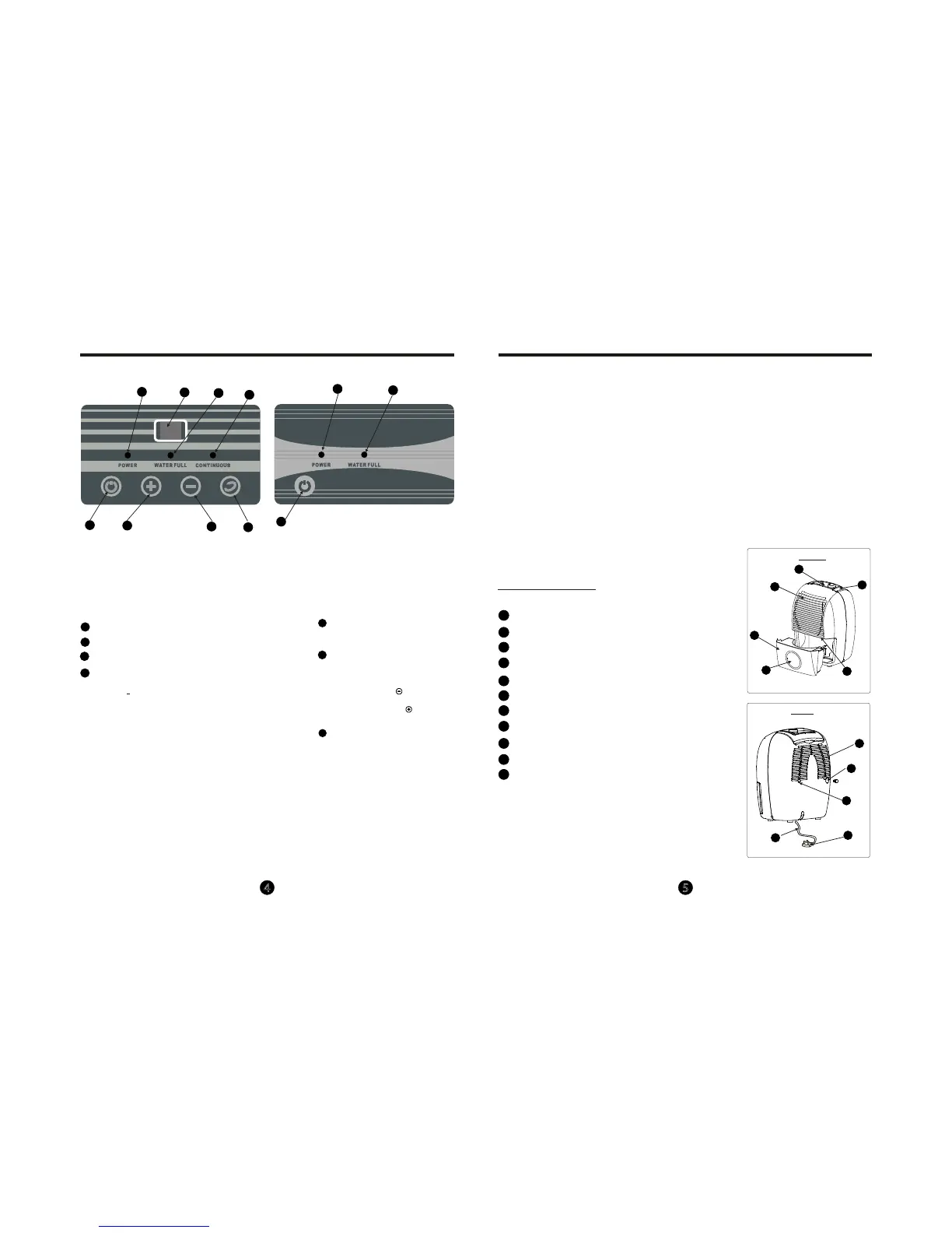
CONTROL PADS ON THE DEHUMIDIFIER
11
22
33
55
55
11
22
44
66
66
77
Control panel(1)
Control panel(2)
33
11
22
44
In dic a t o r l ig ht s
Power on indicator light(green)
Continuous operation on indicator light(green)
Bucket full indicator light(red)
Dis play
S hows the s et % humidity level while s etting, then s hows
the actual(+5% accuracy) room % humidity level.
E rror Codes :
E 1- Humidity s ensor error--Unplug the unit and plug
it back in. If error repeats, call for service.
E 2- Temperature s ensor error-- Unplug the unit and
plug it back in. If error repeats, call for service.
Protect Codes :
P1- Unit is defrosting-- Allow the unit to automatically
defrost. T he portect will clear after the unit s elf defrosts.
P2- Bucket is f
ull or bucket is not in the right position--
E mpty the bucket and replace in the right position.
55
POWE R P ad
Press to turn the dehumidifier on and o.
66
Continue Pad
S elect for the dehumidifier to operate
continuously for maximum dehumidification
until the bucket is full. T he Humidity s et
control pads cannot be used when
Continuous operation is on.P ress this pad
again to cancel Continuous operation.
77
Humidity S et C ontrol P ads
The humidity level can be s et within a
range of 35%R H(R elative H umidity) to 80%
R H(R elative H umidity) in 5% increments.
For drier air, press the pad and s et to a
lower percent value(% ).
For damper air, press the pad a nd set to
a higher percent value(%).
C on tr o l p a ds
Th e co ntr ol pa ne l o f the de hu mi difier yo u purch as ed m ay be lo ok lik e on e of th e fol low ing :
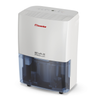
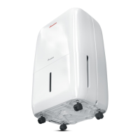
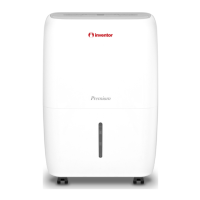
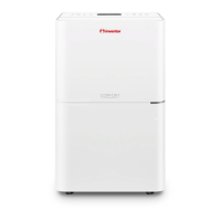
IDENTIFICATION OF PARTS
Identication of parts
O t h e r f e a tu r e s
B ucket Full L ight
Glows when the bucket is ready to be
emptied, or when the bucket is removed
or not replaced in the proper position.
Auto S hut O
The water level control switch s huts o the
dehumidifier when the bucket is full, or when
the bucket is removed or not replaced in the
proper position. When the s etting humidity
is reached, the unit will be s hut o a utomatically.
When frost builds up on the evaporator coils, the
compressor will cycle o and the fan will continue to
run until the frost disappears.
Auto-R es tart(on s ome models )
If the unit breaks o une
xpectedly due to the power cut,
it will restart with the previous function s etting automa-
tically when the power resumes.
Auto Defros t
Power Cord
Air Outlet grille
Drain hose outlet (see page 7)
Air lter (behind the air intake grille)
Power Plug
Power cord band (Used only when storing the unit.)
Front
Rear
Control panel
Air intake grille
Water bucket
Water level window
Handle
77
88
66
99
010
55
33
11
22
44
111
99
010
111
77
55
66
88
33
11
22
44
Fig.2
Fig.3
Wait 3 m inutes befo re r es umin g o pera tion
After the unit ha s s topped, it ca n not be res tart
opertation in the rs t 3 m inutes . T his is to protect
the unit. O peration will automatically s tart a fter
3 minutes.
NOTE: All the pictures in the manual are
for explanation purposes only.Your unit
may be slightly dierent.The actual shape
shall prevail.The operations and functions
are the same.
Fig.1
 Loading...