CAUTION
Inverter DC input power cable and the output cables must be
isolated from each other, and do not put them in the same cable
tray or cable rack.
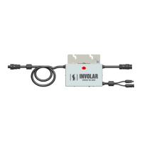
Figure 5-3MAC250 Micro-Inverter detailed Installation diagram
Each of the detailed installation steps is in the above Figure 5-3 shows:
① Attaching the INVOLAR Micro-Inverters to the ranking
② Connecting the INVOLAR Micro-Inverter left side cables.
③ Connecting the INVOLAR Micro-Inverter right side cables.
④ Connect the PV modules
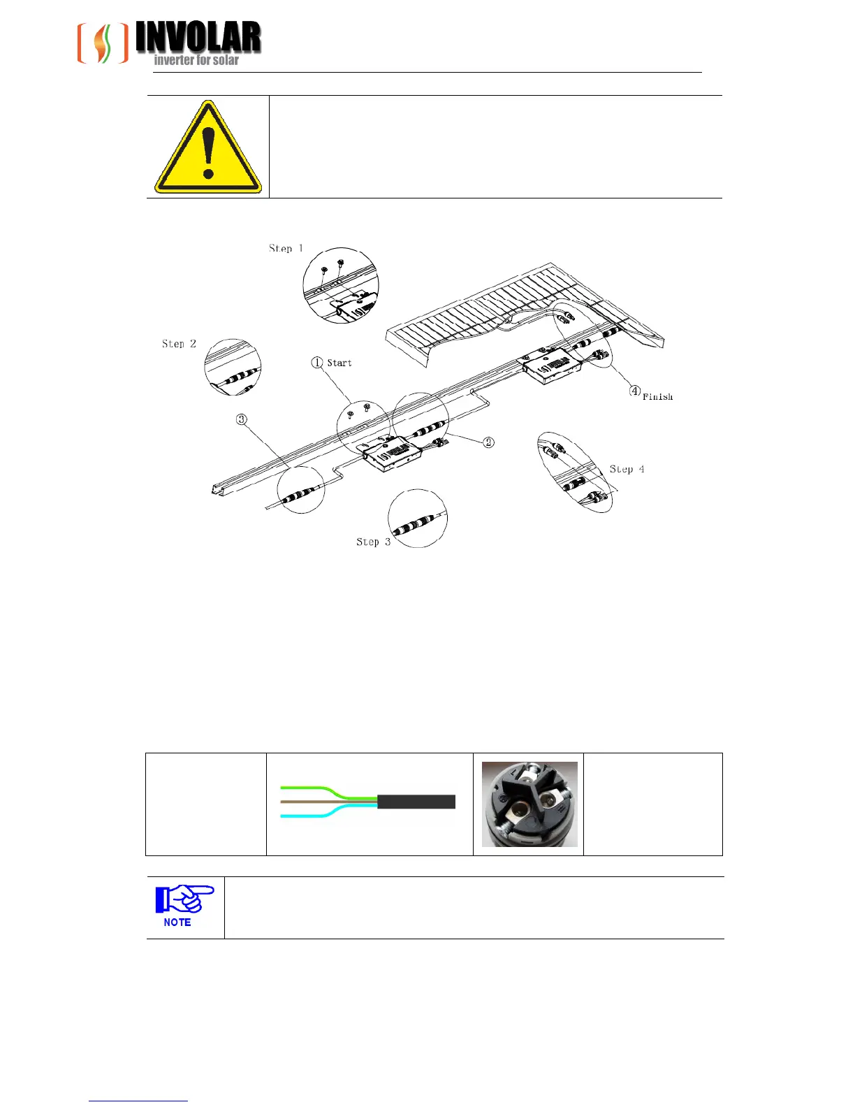
Diagram5-2 AC output cable
Yellow/Green - PE
L -Brown
N -Light Blue
PE - Yellow/Green
Note
MAC250 Micro-Inverter DC connectors are standard, and they should match to the
connectors on PV Modules.