Pag. 13
ENGLISH (Translation of original instructions)
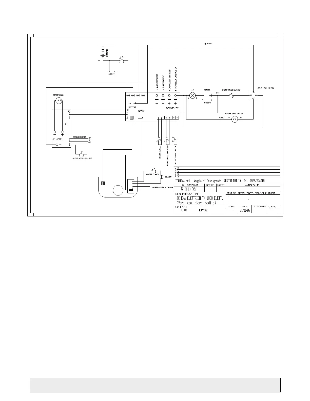
8.2 - WIRING DIAGRAM
COMPONENTS:
Batt. Batteries
M1 Right side brush motor
M2 Centre brush motor
M3 Suction fan motor
M4 Filter shaker motor
M5 Motor differential
M6 Left side brush motor
I.G. Battery disabling key
C.Batt Battery charger socket
Int.1 Side brush micro
Int.2 Accelerator micro
Int.3 Centre brush micro
F1 1.25A 250V fuse
F2 50A bar fuse
Pot.1 Speed regulation potentiometer
TR1 Brake regulation trimmer
Comm.1 Function switch
Comm.2 Direction switch
P1 Horn button
C Horn
CH Key switch
SC1 Battery charge display card
SC2 Card with hour meter