1. Overview
The iPECS ES-3000/3000G is a family of fully managed Layer 2 switches that sup-
port enterprise-class Layer 2 switching features including advanced QoS, security and
simplied and intuitive management features allowing network administrators to build
high performing robust network affordably.
The iPECS ES-3000 series comes in 4 models from Fast Ethernet to Gigabit Ether-
net. The ES-3026 and ES-3026P are Fast Ethernet Layer 2 switches with 24 10/100
BASE-TX ports, and two Small Form Factor Pluggable (SFP) transceiver slots that op-
erate in combination with 10/100/1000 BASE-T ports 25 ~ 26. The ES-3024G and ES-
3024GP are Gigabit Ethernet Layer 2 switches with 24 10/100/1000 BASE-T ports,
and four Small Form Factor Pluggable (SFP) transceiver slots that operate in combi-
nation with ports 21~24. The ES-3026P and ES-3024GP also provide PoE power to
connected devices.
2. Installing the Switch
2.1 Selecting a Site
• The site should :
- be at the center of all the devices you want to link and near a power outlet.
- be able to maintain its temperature within 0 to 50°C (32 to 122°F) and its humidity
within 10% to 90%, non-condensing.
- provide adequate space (approximately two inches) on all sides for proper air ow.
- be accessible for installing, cabling and maintaining the devices.
- allow the status LEDs to be clearly visible.
• Make sure twisted-pair cable is always routed away form power lines, uorescent
lighting xtures and other sources of electrical interference, such as radios and
transmitters.
• Make sure that the units is connected to a separate grounded power outlet that
provides 100 to 240 VAC, 50 to 60 Hz, is within 2 m (6.6 feet) of each device and
is powered from an independent circuit breaker. As with equipment, using a lter or
surge suppressor is recommended.
ES-3024G
ES-3026
ES-3024GP
ES-3026P
2.2 Rack Mounting
The switch can be mounted in a standard 19-inch equipment rack.
Before rack mounting the switch, pay particular attention to the following factors :
• Temperature : Since the temperature within a rack assembly may be higher than the
ambient room temperature, check that the rack-environment temperature is within
the specied operating temperature range. (0°C to 50°C)
• Mechanical Loading : Do not place any equipment on top of the rack-mounted unit.
• Circuit Overloading : Be sure that the supply circuit to the rack assembly is not
overloaded.
• Grounding : Rack-mounted equipment should be properly grounded. Particular at-
tention should be given to supply connections other than direct connections to the
mains.
To rack-mount devices :
Step 1 : Attach the brackets to the device
using the screws provided in the
Bracket Mounting Kit.
Step 2 : Mount the device in the rack,
using four rack-mounting screws
(not provided).
Be sure to secure the lower rack-
mounting screws rst to prevent
the brackets from being bent by
the weight of the switch.
Step 3 : If installing a single switch only,
go to “3. Powering Up”.
Step 4 : If installing multiple switches,
mount them in the rack, one
below the other.
2.3 Desktop or Shelf Mounting
Step 1 : Attach the four adhesive foot pads
to the bottom of the rst switch.
Step 2 : Set the device on a at surface
near an AC power source, mak-
ing sure there are at least two
inches of space on all sides for
proper air ow.
Step 3 : If installing a single switch only,
go to “3. Powering Up”.
Step 4 : If Installing multiple switches,
attach four adhesive foot pads
to each one. Place each device
squarely on top of the below.
2.4 Installing an Optional SFP Transceiver
The SFP slots support the following optional SFP transceivers :
• 1000BASE-SX
• 1000BASE-LX
• 1000BASE-LH
• 100BASE-FX
To install an SFP transceiver, go the fol-
lowing :
Step 1 : Considering network and cabling
requirements to select an appro-
priate SFP transceiver type.
Step 2 : Insert the transceiver with the
optical connector facing outward
and the slot connector facing
down. Note that SFP transceiv-
ers are keyed so they can only be
installed in one orientation.
Step 3 : Slide the SFP transceiver into the
slot until it clicks into place.
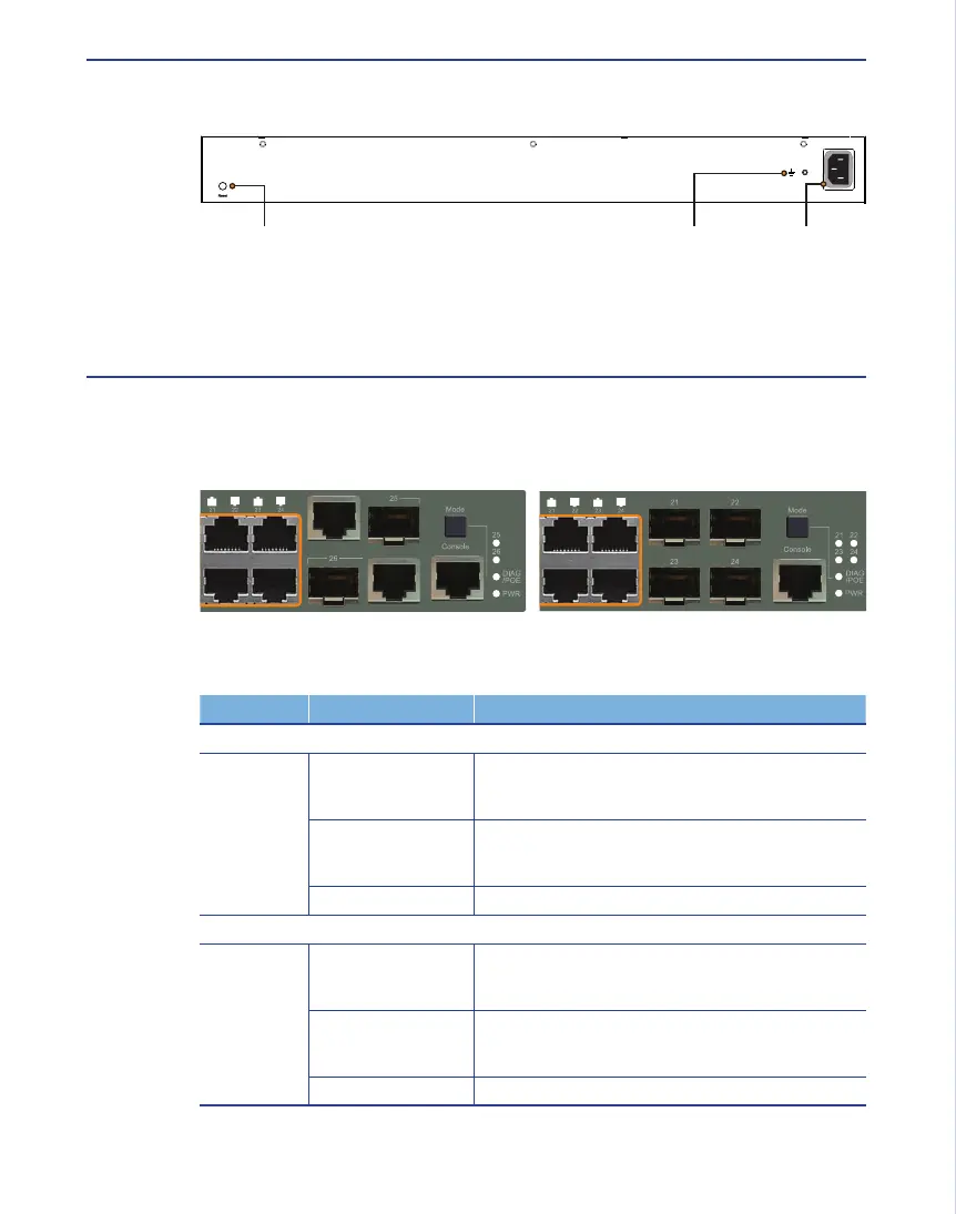
3. Powering Up
Connect the AC power cord to the back of the switch, and then connect the cord to
an AC power outlet.
4. Port and System Status LEDs
The switch includes a display panel for system status and port indications that simplify
installation and network troubleshooting. The LEDs, which are located on the front
panel for easy viewing, are shown below and described in the following tables.
ES-3026/3026P Fast Ethernet Switch Port Status LEDs
LED CONDITION STATUS
Fast Ethernet Ports (1 ~ 24)
LNK/ACT Amber
Amber Flashing
An amber LED indicates that the port is operating at
10 Mbps.
It ashes when the corresponding port is active.
Green
Green Flashing
A green LED indicates that the port is operating at the
maximum speed 100 Mbps.
It ashes when the corresponding port is active.
Off There is no valid link on the port.
SFP Gigabit Ethernet Ports (25 ~ 26)
LNK/ACT Amber
Amber Flashing
An amber LED indicates that the port is operating at
10/100 Mbps.
It ashes when the corresponding port is active.
Green
Green Flashing
A green LED indicates that the port is operating at the
maximum speed 1000 Mbps.
It ashes when the corresponding port is active.
Off There is no valid link on the port.
AC 100-240V, 50-60Hz, 3A
Terminate the wire in an
earthed grounding point.
Attach an insulated grounding
wire, with a metal screw, to
the marked grounding point.
1.
2.
Note : SFP transceivers are hot-swappable. The switch does not need to be pow-
ered off before installing or removing the transceiver. However, always rst
disconnect the network cable before removing the transceiver.
Note : SFP transceivers are not provided in this switch package.
AC 100-240V, 50-60Hz, 3A
Reset Button Power InletGrounding Point
ES-3024G/3024GP Gigabit Ethernet Switch Port Status LEDs
LED CONDITION STATUS
Gigabit Ethernet Ports (1 ~ 24)
LNK/ACT Amber
Amber Flashing
An amber LED indicates that the port is operating at
10/100 Mbps.
It ashes when the corresponding port is active.
Green
Green Flashing
A green LED indicates that the port is operating at the
maximum speed 1000 Mbps.
It ashes when the corresponding port is active.
Off There is no valid link on the port.
SFP Ethernet Ports (21 ~ 24)
LNK Green It indicates that a SFP transceiver is inserted.
Off There’s no SFP transceiver inserted.
ES-3000/3000G Switch System Status LEDs
LED CONDITION STATUS
PWR Green Internal power operates normally
Off No power supply plugged
Diag Amber System Diagnostic in progress
Amber Flashing System Diagnostic Fail
Green System Diagnostic test OK
Green Flashing It ashes while booting.
PoE
(When
Mode button
pressed)
Amber It indicates that the port’s LEDs display PoE status.
Amber Flashing It indicates that power budget reached maximum
value or power budget under and including 95% for
whole system.
ES-3026P ES-3024GP
 Loading...