Basic info about blood pressure
Systolic pressure means that the ventricles contract and pump out blood, increasing the blood pressure. The diastolic pressure
means that the ventricles relax so the blood pressure decreases.
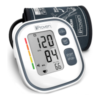
AHA indicator
After each measurement an arrow indicates the corresponding AHA category color on the left of the display. The colors represent
the dierent categories of the American Heart Association blood pressure classication as depicted in the chart below.
Electromagnetic compatibility measures
Please pay attention to the precautions of EMC
(Electromagnetic Compatibility) of this Monitor. The
Blood Pressure Monitor must be installed and used
according to the EMC information shown in this manual.
The device can be aected by portable and mobile RF
communication equipment.
Remove any devices that emit electromagnetic elds
such as mobile phones from nearby the device.
The Blood Pressure Monitor has been tested and
inspected to guarantee a proper performance.
Do not store or use this Monitor with other electric
equipment.
Manufacturer’s declaration on Electromagnetic Immunity for all ME Equipments and Systems Manufacturer’s declaration on Electromagnetic Immunity for all ME Equipments
and Systems that do not provide LIFE-SUPPORTING
The safe distances between portable and mobile RF communications
equipment, ME Equipments and Systems that are not LIFE-SUPPORTING
Changes in blood pressure
There are many factors that cause the
blood pressure to change. Weather,
emotions, stress, food, physical activities;
all these inuence the variations in
the blood pressure. Bear in mind that
measuring in clinical settings tend to
cause the blood pressure to increase.
This is called “white coat eect”.
Error messages and FAQ Important symbols on the monitor
PROBLEM SYMPTOM CHECK THIS REMEDY
No power
Low
batteries
Error
message
Display will not
light up.
Batteries are exhausted.
Replace with new batteries
Insert the batteries
correctly
Replace with new batteries
Batteries are inserted
incorrectly.
Display is dim or
show
Batteries are low.
E 01 shows
E 03 shows
E 04 shows
EExx,shows on
the display.
A calibration error
occurred.
(XX can
be some digital symbol,
such as 01, 02,etc., if
this similar situation
appear, all belong to
calibration error.)
Retake the measurement.
If the problem persists,
contact the retailer or our
customer service
department for further
assistance.Refer to the
warranty for contact
information and return
instructions.
The treatment of the
measurement failed.
E 02 shows
The cuff is too tight
or too loose.
Refasten the cuff and then
measure again.
The monitor
detected motion
while measuring.
Movement can affect the
measurement.Relax for a
moment and then
measure again.
Relax for a moment and
then measure again.
The measurement
process does not
detect the pulse
signal.
Loosen the clothing on
the arm and then
measure again.
Warning
message
Relax for a moment.
Refasten the cuff and then
measure again. If the
problem persists, contact
your physician.
“out ” shows
Out of measurement
range
About 22cm~42cm
Type BF applied part
Power supply
Display mode
Measurement mode
Oscillographic testing mode
Measurement range
Measurement perimeter
of the upper arm
Weight
Approx.260g(Excluding the dry cells and cuff)
External dimensions
Attachment
Mode of operation
Continuous operation
Degree of protection
Protection against
ingress of water
Accuracy
Normal working condition
Storage & transportation
condition
Software Version A01
Pressure:
5℃-40℃within±3mmHg(0.4kPa)
Pulse value:±5%
Rated cuff pressure:
0mmHg~299mmHg(0kPa ~ 39.9kPa)
Measurement pressure:
SYS: 60mmHg~230mmHg (8.0kPa~30.7kPa)
DIA: 40mmHg~130mmHg (5.3kPa~17.3kPa)
Pulse value: (40-199)beat/minute
IP21 It means the device could protected against
solid foreign objects of 12.5mm and greater, and
protect against vertically falling water drops.
Device Classification
Battery Powered Mode:
Internally Powered ME Equipment
AC Adaptor Powered Mode: Class II ME Equipment
A temperature range of :+5°C to +40°C
A relative humidity range of 15% to 90%,
non-condensing, but not requiring a water
vapour partial pressure greater than 50 hPa
An atmospheric pressure range of :
700 hPa to 1060 hPa
Temperature:-20°C to +60°C
A relative humidity range of ≤ 93%,
non-condensing, at a water vapour pressure
up to 50hPa
Symbol for “THE OPERATION
GUIDE MUST BE READ”
Symbol for “MANUFACTURER”
Symbol for “SERIAL NUMBER”
Symbol for “TYPE BF APPLIED
PARTS”
Symbol for “DIRECT CURRENT
”
Symbol for “ENVIRONMENT
PROTECTION - Electrical waste
products should not be disposed of
with household waste. Please recycle
where facilities exist. Check with your
local authority or retailer for recycling
advice”
Symbol for “MANUFACTURE
DATE”
Caution: These notes must be
observed to prevent any damage
to the device.
The Green Dot is the license
symbol of a European
network of industry-funded
systems for recycling the
packaging materials of
consumer goods.
Symbol for “Recycle”
Complied European Standards List
EN ISO 14971:2012 / ISO 14971:2007 Medical devices -
Application of risk management to medical devices
EN 980:2008 Symbols for use in the labelling of medical devices
EN 1041:2008 Information supplied by the manufacturer of medical
devices
EN 60601-1:2006/ IEC 60601-1:2005+A1:2012 Medical electrical
equipment - Part 1: General requirements for basic safety and
essential performance
EN 60601-1-11:2010/ IEC 60601-1-11:2015 Medical electrical
equipment - Part 1-11: General requirements for basic safety and
essential performance - Collateral standard: Requirements for medical
electrical equipment and medical electrical systems used in the home
healthcare environment
EN 60601-1-2:2015/ IEC 60601-1-2:2014 Medical electrical
equipment - Part 1-2: General requirements for basic safety and
essential performance - Collateral standard: Electromagnetic
compatibility - Requirements and tests
EN ISO 81060-1:2012 Non-invasive sphygmomanometers - Part 1:
Requirements and test methods for non-automated measurement type
EN 1060-3:1997+A2:2009 Non-invasive sphygmomanometers -
Part 3: Supplementary requirements for electro-mechanical blood
pressure measuring systems
EN 1060-4:2004 Non-invasive sphygmomanometers - Part 4: Test
procedures to determine the overall system accuracy of automated
non-invasive sphygmomanometers
EN 60601-1-6:2010/IEC 60601-1-6:2010+A1:2013 Medical
electrical equipment - Part 1-6: General requirements for basic safety
and essential performance - Collateral standard: Usability
EN 62366:2008/
IEC 62366-1:2015 Medical devices - Application
of usability engineering to medical devices
EN 62304:2006/AC: 2008 / IEC 62304:2006 Medical device
software - Software life-cycle processes
Risk management
Labeling
User manual
General Requirements
for Safety
Electromagnetic
compatibility
Performance
requirements
Clinical investigation
Usability
Software life-cycle
processes
Bio-compatibility
ISO 10993-1:2009 Biological evaluation of medical devices- Part
1: Evaluation and testing within a risk management process
ISO 10993-5:2009 Biological evaluation of medical devices -
Part 5: Tests for in vitro cytotoxicity
ISO 10993-10:2010 Biological evaluation of medical devices -
Part 10: Tests for irritation and skin sensitization
ISO 15223-1:2012 Medical devices. Symbols to be used with
medical device labels, labelling and information to be supplied. Part 1 :
General requirements
IEC 80601-2-30:2013 Medical electrical equipment- Part 2-30:
Particular requirements for the basic safety and essential
performance of automated non-invasive sphygmomanometers
ISO 81060-2:2013 Non-invasive sphygmomanometers - Part 2:
Clinical validation of automated measurement type
Guidance and manufacturer’s declaration – electromagnetic emissions
RF emissions
CISPR 11
Group 1
Class B
Class A
Complies
Compliance
Harmonic emissions
IEC 61000-3-2
Voltage fluctuations/
flicker emissions
IEC 61000-3-3
RF emissions
CISPR 11
Emissions test Electromagnetic environment - guidance
The device is intended for use in the electromagnetic environment specified below. The customer or the
user of the device should assure that it is used in such an environment.
The device uses RF energy only for its internal
function. Therefore, its RF emissions are very low
and are not likely to cause any interference in nearby
electronic equipment.
The device is suitable for use in all establishments,
other than domestic and those directly connected to
the public low-voltage power supply network that
supplies buildings used for domestic purposes.
Guidance and manufacturer’s declaration – electromagnetic immunity
Immunity test
±8 kV contact
±15 kV air
±8 kV contact
±15 kV air
±2 kV
power supply lines:
line(s) to line(s): ±1 kV
line(s) to earth: ±2 kV
0% 0.5 cycle
At 0°, 45°, 90°, 135°,
180°,225°,270° and 315°
0% 1 cycle
and 70% 25/30 cycles
Single phase: at 0
0% 300 cycle
30 A/m
50Hz/60Hz
NOTE U
T
is the a.c. mains voltage prior to application of the test level.
Compliance level
Electrostatic
discharge (ESD)
IEC 61000-4-2
Electromagnetic
environment - guidance
30 A/m
50Hz/60Hz
Power frequency
(50Hz/60Hz)
magnetic field
IEC 61000-4-8
Voltage dips,
short interruptions
and voltage
variations on
power supply
input lines
IEC 61000-4-11
Electrical fast
transient/burst
IEC 61000-4-4
Surge
IEC61000-4-5
input/output lines:
±1 kV
The device is intended for use in the electromagnetic environment specified below. The customer or the
user of the device should assure that it is used in such an environment.
IEC 60601 test level
Floors should be wood, concrete
or ceramic tile. If floors are
covered with synthetic material,
the relative humidity should be at
least 30%.
±2 kV
power supply lines:
100 kHz repetition
frequency
line(s) to line(s): ±1 kV
100 kHz repetition
frequency
Mains power quality should be
that of a typical commercial or
hospital environment.
Mains power quality should be
that of a typical commercial or
hospital environment.
Mains power quality should be
that of a typical commercial or
hospital environment.
Power frequency magnetic fields
should be at levels characteristic
of a typical location in a typical
commercial or hospital
environment.
0% 0.5 cycle
At 0°, 45°, 90°, 135°,
180°,225°,270° and
315°
0% 1 cycle
and 70% 25/30 cycles
Single phase: at 0
0% 300 cycle
Guidance and manufacturer’s declaration – electromagnetic immunity
Immunity test
Compliance
level
IEC 60601
Test level
Conducted RF
IEC 61000-4-6
Radiated RF
IEC 61000-4-3
10V/m, 80% Am
at 1kHz
150 kHz to
80 MHz:
3 Vrms
6Vrms (in ISM
and amateur
radio bands)
80% Am at 1kHz
Electromagnetic environment - guidance
NOTE 1 A t 80 MHz and 800 MHz, the higher frequency range applies.
NOTE 2 T hese guidelines may not apply in all situations. Electromagnetic propagation is affected by
absorption and reflection from structures, objects and people.
a
Field strengths from fixed transmitters, such as base stations for radio (cellular / cordless)
telephones and land mobile radios, amateur radio, AM and FM radio broadcast and TV broadcast
cannot be predicted theoretically with accuracy. To assess the electromagnetic environment due to
fixed RF transmitters, an electromagnetic site survey should be considered. If the measured field
strength in the location in which the device is used exceeds the applicable RF compliance level
above, the device should be observed to verify normal operation. If abnormal performance is
observed, additional measures may be necessary, such as re-orienting or relocating the device.
Over the frequency range 150 kHz to 80 MHz, field strengths should be less than 3V/m.
b
The device is intended for use in the electromagnetic environment specified below. The customer or the
user of the device should assure that it is used in such an environment.
150 kHz to
80 MHz:
3 Vrms
6Vrms (in ISM
and amateur
radio bands)
80% Am at 1kHz
Portable and mobile RF communications
equipment should be used no closer to any part
of the device, including cables, than the
recommended separation distance calculated
from the equation appropriate for the frequency
of the transmitter.
Recommended separation distances:
d=0.35;
d=1.2
10V/m, 80% Am
at 1kHz
80 MHz to 800 MHz:
d=1.2
800 MHz to 2.7 GHz:
d=2.3
where,
P is the maximum
output power rating of the
transmitter in watts (W)
according to the
transmitter manufacturer,
d is the recommended
separation distance in
meters (m). Field
strengths from fixed RF
transmitters, as
determined by an
electromagnetic site
survey, should be less
than the compliance level
in each frequency range.
Interference may occur in
the vicinity of equipment
marked with the following
symbol:
150 kHz to 80 MHz 8 0 MHz to 800 MHz 800 MHz to 2.7 GHz
Recommended separation distances between portable and mobile RF communications
equipment and the device.
Rated maximum output
power of transmitter
(W)
Separation distance according to frequency of transmitter (m)
0.01
0.1
1
10
100
0.12 0.12
0.38
1.2
3.8
12
0.23
0.73
2.3
7.3
23
The device is intended for use in an electromagnetic environment in which radiated RF disturbances are
controlled. The customer or the user of the device can help prevent electromagnetic interference by
maintaining a minimum distance between portable and mobile RF communications equipment
(transmittters) and the device as recommended below, according to the maximum output power of the
communications equipment.
For transmitters rated at a maximum output power not listed above, the recommended separation
distance
d in metres (m) can be estimated using the equation applicable to the frequency of the
transmitter, where P is the maximum output power rating of the transmitter in watts (W) according to the
transmitter manufacturer.
NOTE 1 At 80 MHz and 800 MHz, the separation distance for the higher frequency range applies.
NOTE 2 These guidelines may not apply in all situations. Electromagnetic propagation is affected by
absorption and reflection from structures, objects and people.
FCC Statement
This device complies with Part 15 of the FCC
Rules. Operation is subject to the following two
conditions: (1) this device may not cause harmful
interference, and (2) this device must accept any
interference received, including interference that
may cause undesired operation.
CAUTIONS
• When using this device, please pay attention to the following situation which may interrupt blood ow and inuence
blood circulation of the patient, thus cause harmful injury to the patient: connection tubing kinking too frequent and consecutive multiple
measurements; the application of the cu and its pressurization on any arm where intravascular access or therapy, or an arterio-venous (A-V) shunt, is
present; inating the cu on the side of a mastectomy.
• Warning: Do not apply the cu over a wound;otherwise it can cause further injury.
• Do not inate the cu on the samb limb which other monitoring ME equipment is applied around simultaneously, because this could cause
temporary loss of function of those simultaneously-used monitoring ME equipment.
• On the rare occasion of a fault causing the cu to remain fully inated during measurement, open the cu immediately.
• Prolonged high pressure (cu pressure > 300mmHg or constant pressure > 15mmHg for more than 3 minutes) applied to the arm
may lead to an ecchymosis.
• Please check that operation of the device does not result in prolonged impairment of patient blood circulation.
• When measurement, please avoid compression or restriction of the connection tubing.
• The device cannot be used with HF surgical equipment at the same time.
• The ACCOMPANYING DOCUMENT shall disclose that the SPHYGMOMANOMETER was clinically
investigated according to the requirements of ISO 81060-2:2013.
• To verify the calibration of the AUTOMATED SPHYGMOMANOMETER, please contact the manufacturer.
• This device is contraindicated for any female who may be suspected of, or is pregnant. Besides providing inaccurate readings,
the eects of this device on the fetus are unknown.
• Too frequent and consecutive measurements could cause disturbances in blood circulation and injuries. This unit is not suitable for continuous
monitoring during medical emergencies or operations. Otherwise, the patient’s arm and ngers will become anaesthetic, swollen and even purple
due to a lack of blood.
• When not in use, store the device with the adapter in a dry room and protect it against extreme moisture, heat, lint,
dust and direct sunlight. Never place any heavy objects on the storage case.
• This device may be used only for the purpose described in this booklet. The manufacturer cannot be held liable
for damage caused by incorrect application.
Authorized Component
1. Please use the iProvèn authorized adapter. (not
included)
Guidance and manufactures - electromagnetic Immunity
Adapter
Model: KH0601000UW
Input: AC 100-240V
50/60Hz 0.4A Max
Output: 6V 1000mA
Test
Frequency
(MHz)
385
0.32 7
The device is intended for use in the electromagnetic environment specified below. The customer or the
user of the device, should assure that it is used in such an environment.
NOTE If necessary to achieve the IMMUNITY TEST LEVEL, the distance between the transmitting antenna
and the ME EQUIPMENT or ME SYSTEM may be reduced to 1 m. The 1 m test distance is permitted by
IEC 61000-4-3.
Radiated RF
IEC61000-4-3
(Test
specifications
for
ENCLOSURE
PORT
IMMUNITY to
RF wireless
communica-
tions
equipment)
Band a)
(MHz)
Service a) Modulation b)Modulation b)
(W)
Distance (m)
IMMUNITY
TEST
LEVEL
(V/m)
380-390 TETRA
400
Pulse
modulation b)
18Hz
1.8
450 380-390
GMRS 460,
FRS 460
FM c) ± 5kHz
deviation 1kHz
sine
20 .3 28
710 704-787
745
780
LTE Band
13,
17
Pulse
modulation b)
217Hz
0.20 .3 9
810
870
930
800-960
GSM
800/900,
TETRA 800,
iDEN 820,
CDMA 850,
LTE Band 5
Pulse
modulation b)
18Hz
2
0.32 8
1720
1845
1970
1700-
1990
GSM 1800;
CDMA 1900;
GSM 1900;
DECT;
LTE Band 1,
3,
4,25; UMTS
Pulse
modulation b)
217Hz
2
0.32 8
2
0.32 82450 2400-
2570
Bluetooth,
WLAN,
802.11
b/g/n, RFID
2450, LTE
Band 7
Pulse
modulation b)
217 Hz
5240
5240
5785
5100-
5800
WLAN
802.11
a/n
Pulse
modulation b)
217 Hz
0.2
0.39
a) For some services, only the uplink frequencies are included.
b) The carrier shall be modulated using a 50% duty cycle square wave signal.
c) As an alternative to FM modulation, 50% pulse modulation at 18 Hz may be used because while it does
not represent actual modulation, it would be worst case.
The MANUFACTURER should consider reducing the minimum separation distance, based on RISK
MANAGEMENT, and using higher IMMUNITY TEST LEVELS that are appropriate for the reduced
minimum separation distance. Minimum separation distances for higher IMMUNITY TEST LEVELS shall be
calculated using the following equation:
E=
Where P is the maximum power in W, d is the minimum separation distance in m, and E is the IMMUNITY
TEST LEVEL in V/m.
Normal
Prehypertension
less than 120
90 or higher
Higher than 120
Higher than 180
less than 80
less than 80
120-129
High Blood Pressure
(hypertension) Stage 1
High Blood Pressure
(hypertension) Stage 2
Hypertensive Crisis
(Emergency care needed)
130-139
140 or higher
80-89
and
and
or
or
and/or
Blood Pressure
Category
Systolic
mm HG (upper#)
Diastolic
mm Hg (lower#)
Green
Yellow
Orange
Dark
Orange
Red
 Loading...