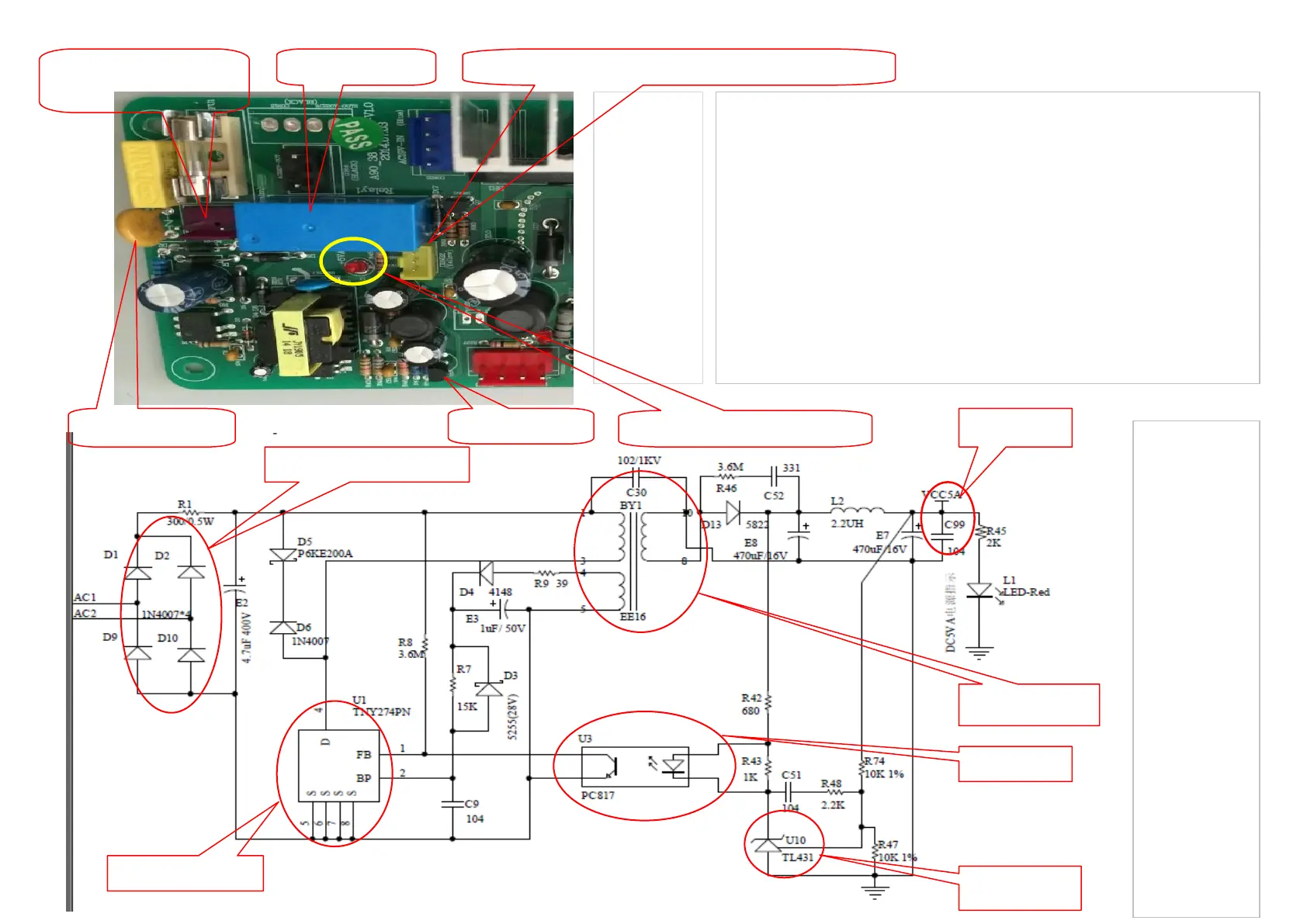
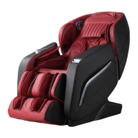
Figure 4, the physical map of drive power
supply and part of DC5V switch power
supply
The relationship of DC5V switch power supply and drive power supply:
AC220V input to CON11 on the driver board
→The driver board get DV5V switch power supply
→IC and remote controller have DC5V working voltage
→Remote controller can start to work
→Relay 105LM, control the power supply, its coil get the electricity
→CN016 get AC220V power supply
→Driver circuit get AC110V and AC24V power supply
→Massage chair work in regular


 To Next Page