EasyManua.ls Logo

Iridium 9602 - User Manual

Iridium 9602
32 pages
Print Icon
To Next Page IconTo Next Page
Loading...
Proprietary & Confidential Information
Distribution of guide restricted to product developers only. • Information contained in this guide is subject to change without notice.
Iridium 9602/9602N SBD Transceiver
Development
Guide
MAN0017
Iridium Satellite LLC
1750 Tysons Boulevard, Suite 1400
McLean, VA 22102 USA
www.iridium.com
Toll Free: +1.866.947.4348 [US Only]
International +1.480.752.5155
email:
info@iridium.com
Question and Answer IconNeed help?

Do you have a question about the Iridium 9602 and is the answer not in the manual?

Summary

3 Electrical Interfaces

3.1 User Connector

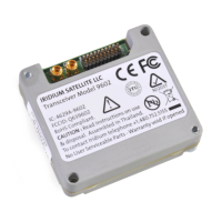
Describes the main multi-pin connector for host system interaction, including pin allocation.

3.2 DC Power Interface

Explains power supply requirements, input voltage range, and typical power consumption.

3.3 Serial Data Interface

Covers the serial communication protocols, 9-wire/3-wire operation, and modes.

3.4 Hardware Failure Reporting

Details how the transceiver reports internal hardware issues via unsolicited result codes.

4 RF Interface

4.1 RF Connector Types

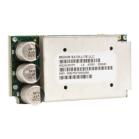
Specifies the types of RF connectors used on the module for motherboard connection.

4.2 ANT Connector

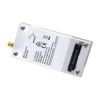
Focuses on the primary RF antenna connector and safety considerations.

4.4 Radio Interface Specifications

Technical parameters for the RF interface, including frequency range and impedance.

5 AT Command Set Description

1 Product Overview

2 Physical Specification

Iridium 9602 Specifications

General IconGeneral
BrandIridium
Model9602
CategoryTransceiver
LanguageEnglish

Related product manuals