Page 9 of 13
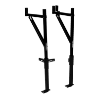
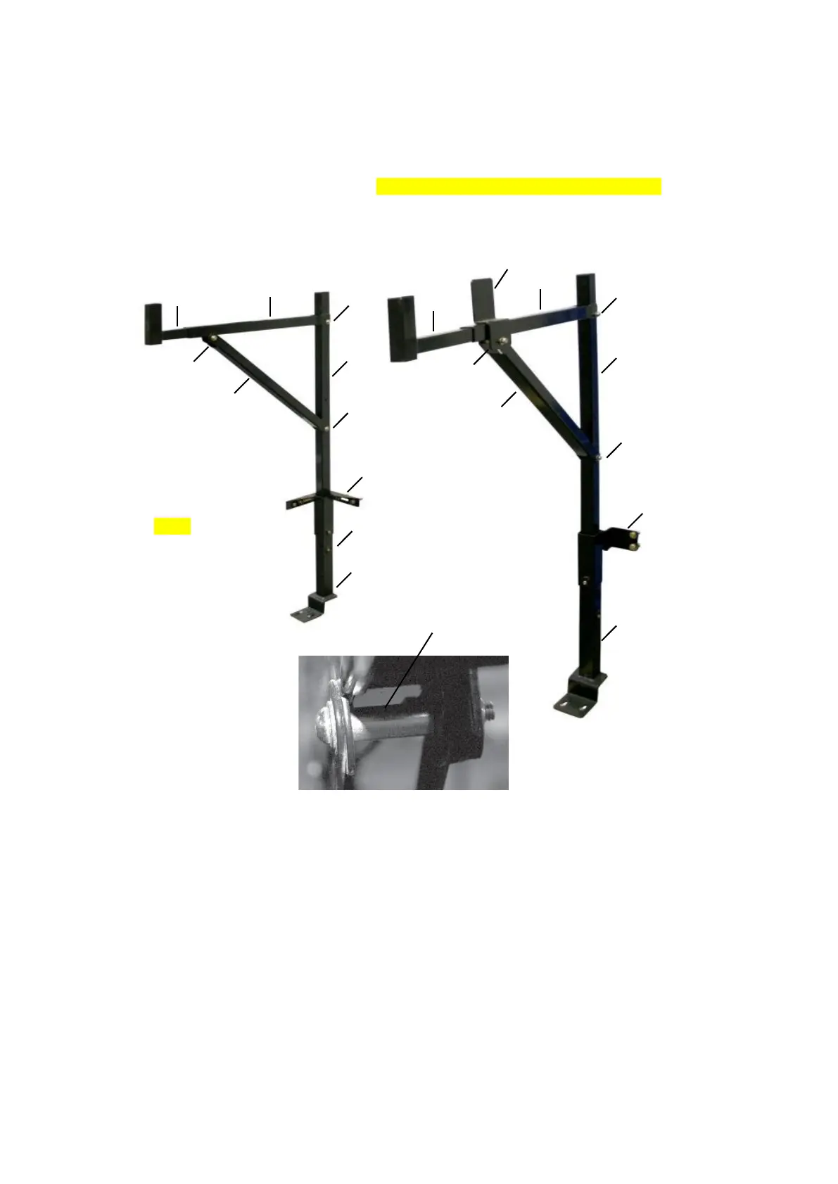
Step 4- Refer to Fig. 4
1. Assemble the upper arm using 5/16"Button Head Bolts (G), 5/16"Flat Washers (K) and 5/16" Lock
Nuts (J). Use a 5/16" Button Head Bolt (H) to attach the Ladder Stop (5) with the Spacer (M) in
the gap of the Horizontal Cross Arm (7). Insert the Adjustable Arm (8) into the Horizontal Cross
Arm (7) and adjust to the desired width. Secure it using M8 x 65 Button Head Bolt (H). Insert the
Uprights (3) into the Upright Supports (6). Secure using set screws (c).
Step 5
Tighten all hardware.