18 of 30
4.2 Thawing
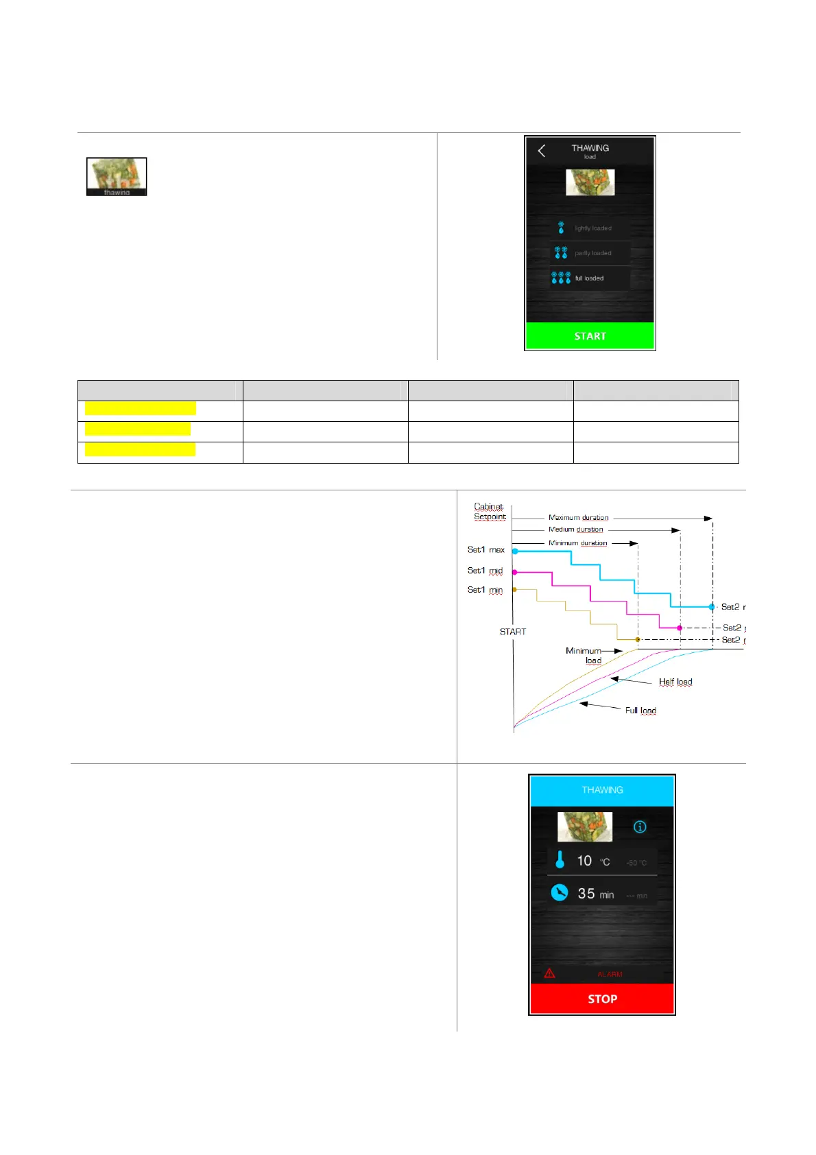
Pressing this area enables selection of a thawing
cycle, managed according to the load of product
to be thawed, in compliance with the maximum quantity
stated by the manufacturer.
To make it easy, the quantity of product to be selected is
divided into three load bands for each of which the controller
will load three different sets of parameters, according to the
following framework.
Load band Initial cabinet set point Final cabinet set point Cycle duration
Light loaded cabinet r25 r28 r32
Half loaded cabinet r26 r29 r33
Full loadded cabinet r27 r30 r34
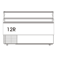
These parameters control the set points and the duration of the
thawing cycle, equally divided into five phases following on from
each other as shown.
- Phase 1 set = initial set point
- Phase 2 set = phase 1 set point + [(initial set point – final set point) / 4]
- Phase 3 set = phase 2 set point + [(initial set point – final set point) / 4]
- Phase 4 set = phase 3 set point + [(initial set point – final set point) / 4]
- Phase 5 set point = final set point
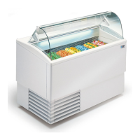
THAWING FAN CONTROL the parameters F29, F30, F31, F32,
F33 an control the ventilation, one for each phase 1..5.
END CYCLE the buzzer sounds and the holding phase is ON, the
set point is r31 for an indefinite period. The fan speed set
parameter F34.
DEFROST is not available, while during the holding phase the
defrost can be set at intervals.
DOOR With open door the unit runs as in normal working cycles.