EasyManua.ls Logo

ISE smart connect Modbus Vaillant - User Manual

ISE smart connect Modbus Vaillant
45 pages
Print Icon
To Next Page IconTo Next Page
Loading...
ise smart connect Modbus Vaillant
Product Manual
Product Manual
ise smart connect Modbus Vaillant
Order no. S-0002-007
Complete set for installation, consisting of the two system components:
- ise smart connect Modbus Vaillant and
- ise eBUS Adapter
Order no. 1-0009-000
- ise smart connect Modbus Vaillant
Order no. 2-0001-003
- ise eBUS Adapter
Valid for firmware version 1.0

Table of Contents

Question and Answer IconNeed help?

Do you have a question about the ISE smart connect Modbus Vaillant and is the answer not in the manual?

Overview

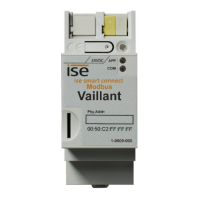
The ise smart connect Modbus Vaillant is a device designed to integrate Vaillant heating systems with a Building Management System (BMS) via Modbus TCP/IP. It acts as a gateway, allowing communication and control between the Vaillant geoTHERM/3 VWS220/3 – 460/3 heat pump and other Vaillant VR60 mixer modules or VR90 remote control units, and a central BMS. The system components include the ise smart connect Modbus Vaillant itself and an ise eBUS Adapter.

Function Description

The primary function of the ise smart connect Modbus Vaillant is to provide a Modbus TCP/IP interface for Vaillant heating systems. This enables external control and monitoring of the heating system by a BMS. The device facilitates the integration of a Vaillant geoTHERM/3 VWS220/3 – 460/3 heat pump and potentially other Vaillant VR60 mixer modules and VR90 remote control units into a Modbus TCP/IP network. The ise eBUS Adapter is essential for connecting the ise smart connect Modbus Vaillant to the Vaillant eBUS, which is the communication bus for Vaillant system components.

The device supports various Modbus functions, including:

  • Read Holding Registers (0x03): Allows reading of current values from the heating system.
  • Read Input Registers (0x04): Allows reading of input values from the heating system.
  • Write Single Register (0x06): Enables writing a single value to a register in the heating system.
  • Write Multiple Registers (0x16): Enables writing multiple values to registers in the heating system.

It also defines Modbus exception codes for various communication errors, such as illegal function, illegal data address, illegal data value, server failure, and gateway target device failure.

The system allows for configuration of the Modbus TCP/IP port, with a default of 502, and supports a range between 2,000 and 4,000. It can be configured via a web interface, allowing users to set IP addresses, subnet masks, and gateway addresses, and to monitor the status of connected Vaillant units.

Important Technical Specifications

ise smart connect Modbus Vaillant:

  • External Supply Voltage: DC 24 to 30 V ±10%
  • Connection: Bus connection terminal, preferably yellow (+)/white (–)
  • Power Consumption: 1.2 W (with DC 24 V and connected ise eBUS Adapter)
  • IP Communication: Ethernet 10/100 BaseT (10/100 Mbit/s)
  • IP Connection: 1 x RJ45
  • USB Connection: 1 x USB type A (use supplied USB cable, max 3 m length)
  • Supported Protocols: ARP, ICMP, IGMP, UDP/IP, DHCP, AutoIP, Modbus TCP/IP
  • microSD Card: No function
  • Ambient Temperature: 0 °C to +45 °C
  • Storage Temperature: -25 °C to +70 °C
  • Installation Width: 36 mm (2 HP)
  • Installation Height: 90 mm
  • Installation Depth: 74 mm
  • Protection Type: IP20 (compliant with EN60529)
  • Protection Class: III (compliant with IEC 61140)
  • Test Marks: CE

ise eBUS Adapter:

  • Operating Voltage: Supply via eBUS
  • eBUS Connection: Connection terminal
  • USB Connection: 1 x mini USB B
  • eBUS Power Consumption: 0.1 W at 24 V
  • USB Power Consumption: 0.05 W
  • Ambient Temperature: 0 °C to +45 °C
  • Storage Temperature: -25 °C to +70 °C
  • Installation Width: 17.5 mm (1 HP)
  • Installation Height: 90 mm
  • Installation Depth: 74 mm
  • Test Marks: CE

The maximum length of the eBUS connection cable is 125 m. The USB cable supplied with the ise eBUS Adapter should be used, and its length should not exceed 3 m.

Usage Features

The device is designed for easy installation on a top-hat rail as per DIN EN 60715. Vertical mounting is recommended, with the network connection facing downwards. It is crucial to ensure sufficient ventilation and cooling, as the device operates within a temperature range of 0 °C to +45 °C.

LED Status Displays: The device features three status LEDs (LED "APP" green, LED "COM" yellow, and LED (red)) on the upper housing side and two status LEDs on the network connections. These LEDs provide visual feedback on the device's operational status, including:

  • Power supply status: On/Off.
  • Device start-up progress: Indicated by LED "APP" flashing slowly or being green.
  • Operation status: LED "APP" green indicates normal operation.
  • eBUS communication status: LED "APP" flashing patterns indicate eBUS errors or connection issues.
  • Modbus TCP/IP status: LED "COM" yellow indicates normal operation, while flashing or being off indicates Modbus TCP/IP server not running or traffic issues.

Configuration: The device can be configured via a web interface accessible through a browser. This allows for:

  • IP address settings: DHCP or static IP configuration.
  • System dimensioning: Adding and configuring Vaillant units (geoTHERM/3, VR60, VR90).
  • Modbus TCP/IP port configuration: Setting the port number (default 502).
  • BMS integration: Configuration for the building management system.

Factory Reset: The device supports a factory reset function, which can be initiated by pressing and holding the button on the device. This resets the device to its default settings, including the Modbus TCP/IP port and data points.

Firmware Update: Firmware updates can be performed via the web interface. It is recommended to check for updates regularly on the manufacturer's website. The update process involves downloading the firmware file and uploading it through the device's web interface.

Maintenance Features

Troubleshooting: The manual provides a comprehensive troubleshooting guide, including:

  • Downloading log files: If problems occur, log files can be downloaded from the device's web interface to assist in diagnosis.
  • Device status page: The web interface includes a status page that displays MAC address, current IP settings, and installed software version, which are useful for diagnostic purposes.
  • Troubleshooting flow chart: A detailed flow chart helps identify and resolve common issues based on LED indicators and network connectivity. This includes checking cabling, eBUS communication, Modbus Gateway errors, and network settings.

Safety Notes:

  • Electrical Safety: Only qualified electricians should install and mount the device. All applicable accident prevention regulations must be observed.
  • Power Supply: The device must be supplied with voltage by a dedicated power supply unit. The auxiliary voltage output of a KNX power supply unit should not be used for supplying a KNX line.
  • Live Parts: Electric shock is a danger if live parts are touched. The device must be isolated from voltage before working on it.
  • USB Cables: Use only the supplied USB cable. The use of USB cables with a length greater than 3 m is generally not permitted.

Cover Cap: The device includes a cover cap that can be mounted for protection of the power supply connections from dangerous voltage. This cap can be removed by pressing it slightly on the side and pulling it off.

The ise smart connect Modbus Vaillant is designed for long-term operation with minimal maintenance, primarily involving firmware updates and occasional troubleshooting via the web interface.

ISE smart connect Modbus Vaillant Specifications

General IconGeneral
BrandISE
Modelsmart connect Modbus Vaillant
CategoryGateway
LanguageEnglish

Related product manuals