isel- Ê«>VÌʵիiÌÊÊ*
ÓÊÝ
During transportation, please pay attention to the supply and connection cables (remove if
needed) so that they are not damaged. Use only suitable lifting devices.
LÛiÊ>]Êii«ÊÌiÊÌÀ>}Õ>ÀÊÜÀiVÊ>Ü>ÞÃÊ
ÕÌÃ`iÊvÊÌiÊ>ViÊ`ÕÀ}
ÌÀ>ëÀÌ>Ì°
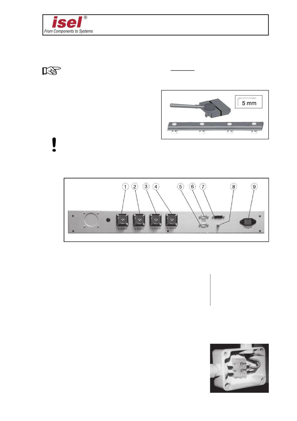
The V>«}ÊÃiÌ is made up by a hand
lever clamping assembly and two stop
bars with mounting hardware for the T-slot
plate.
Ü>ÞÃÊiÃÕÀiÊÌ>ÌÊÌiÊÜÀ«iViÃÊ>ÀiÊ«À«iÀÞÊÃiVÕÀi`°
iVÌÃ to the controller of the machine (type model 1):
➀ Z-axis (Amphenol connector)
➁ X-axis (Amphenol connector)
➂ Y-axis (Amphenol connector)
➃ A-axis (axis of rotation )(Amphenol connector) The pin allocation of
➄ START and STOP push-button (9-pin connector) the connectors ➀ - ➆
➅
hood switch (9-pin Sub D connector) is located in the
➆ POWER / emergency push-button (15-pin connector) technical data
➇ grounding point
➈ tooling machine
For the >VViÃÃÀiÃ] different parts are already pre-installed or prepared for mounting.
For this purpose, also read the information in the appendix.
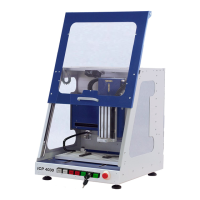
You can connect the cable of a tooling machine to the coupler
terminal block in the branch box at the side of the Z-axis.