Page 9
Installation manual
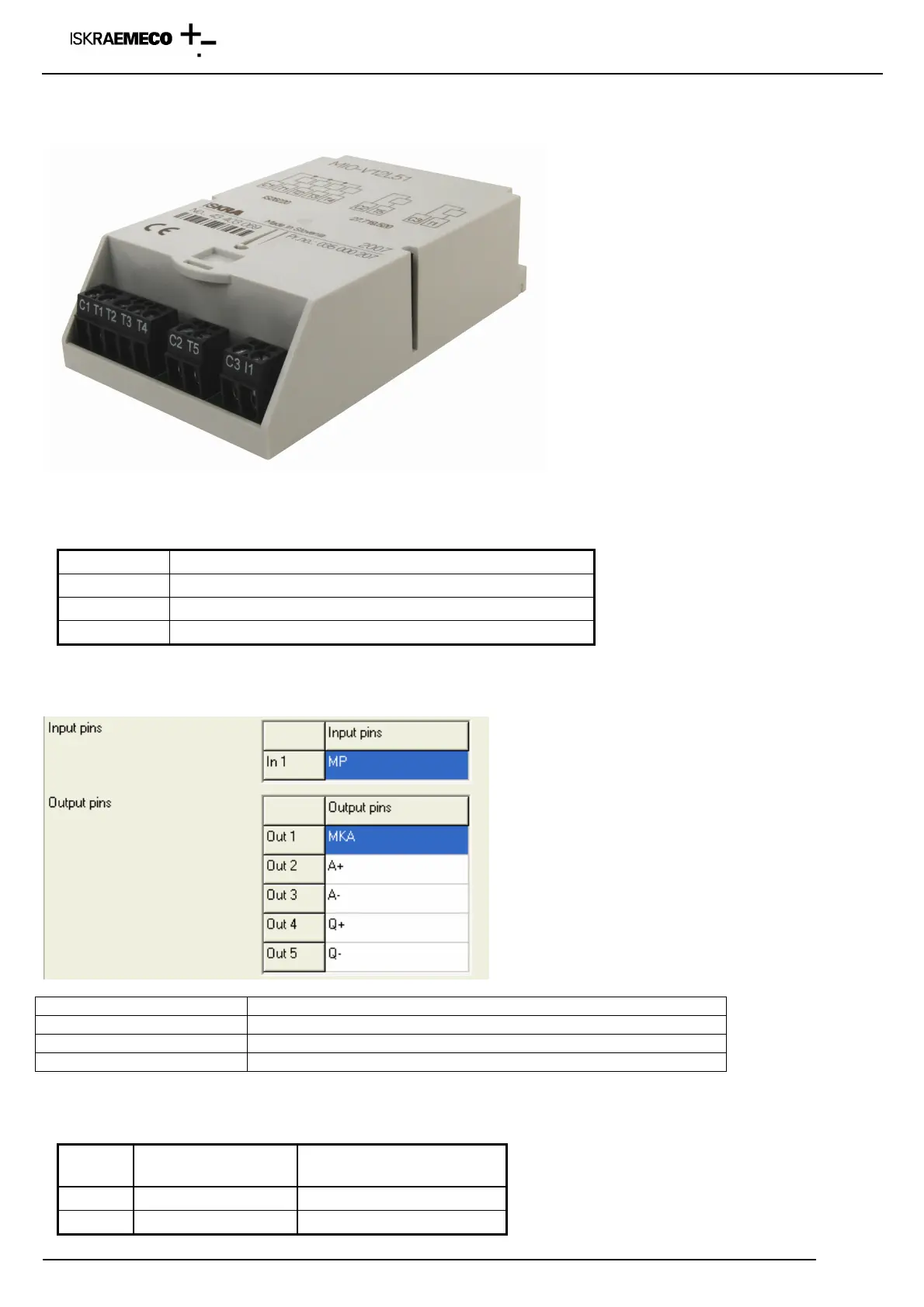
Definition of input terminals – non-programmed input – output module (function is defined by the parameters in
the meter)
Fig. 10: Default »non-programmed« input -output module
Terminal Additional explanation
C1, C2, C3 Common terminal for functional inputs or outputs
I1, I1, I3, I4 Input terminals
T1, …, T8 Output terminals
Function of input (output) terminal is written on the meter connection diagram (sticked on the bottom terminal cover side).
It could be also read out with the MeterView program:
Module designation
MIO-V12L51
1 x input, 4 x OPTOMOS outputs, 1 x OPTOMOS output
MIO-V42L81
4 x input, 4 x OPTOMOS outputs, 4 x OPTOMOS output
MIO-V12L41B11
1 x input, 4 x OPTOMOS outputs, 1 x bistable 5A relay output
Definition of external power supply
Terminal
Terminal
designation
Additional explanation
30 50 – 240 V AC/DC External power supply
31 50 – 240 V AC/DC External power supply


 To Next Page