Page 8
Installation manual
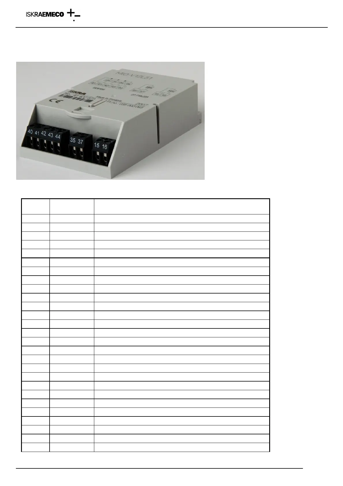
Connection diagram for modules is printed on the module itself and on the label, on the bottom side of the terminal cover.
Definition of input terminals – factory programmed input – output module (function is define in the module)
Fig. 9: Factory programmed input -output module
Terminal
Terminal
designation
Additional explanation
15 COM Common terminal for functional inputs
13, 33 TE1/2, TE3/4 Energy tariff input T1 – T4
14, 34 ME1/2, ME3/4 Demand tariff input M1 – M4
16 MPE External time/measurement period synchronization input
17 MZE External input for disabling of demand measurement
18 MREa Input a for external billing reset
19 MREb Input b for external billing reset
35 COM Common terminal
36 MKA Alarm output
37 MPA Measurement period output
38 ERA+A Energy flow direction +A
39 ERA+R Energy flow direction +R
40 COM Common terminal
41 +AA Pulse output +A
42 -AA Pulse output -A
43 +RA Pulse output +R
44 -RA Pulse output -R
45 RA1 Pulse output RA1
46 RA2 Pulse output RA2
47 RA3 Pulse output RA3
48 RA4 Pulse output RA4
65 COM Common terminal
61, 63 TA1/2, TA3/4 Demand tariff outputs T1 – T4
62, 64 MA1/2, MA3/4 Demand tariff outputs M1 – M4
67 MZA Output for disabled max. demand measurement
68 MRAa Output for external billing reset a
69 MRAb Output for external billing reset b


 To Next Page