Do you have a question about the ISOIL ISOMAG MV110 and is the answer not in the manual?
General safety precautions and guidelines for the safe use and handling of the measuring device.
Explanation of hazard symbols and cautionary statements for safe operation.
Details on converter classification, power supply, and electrical specifications.
Information on operating altitude, humidity range, and ambient temperature limits.
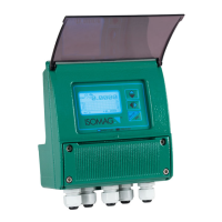
Details provided on the instrument's label, including model and serial number.
Specifications for tightening torques of screws and caps for specific housing materials.
Specifications for tightening torques of screws and caps for stainless steel housing.
Diagrams showing the internal components and layout of the converter.
Important operational advice and attention points regarding the internal lithium battery.
Details on connecting digital outputs, including specifications and diagrams.
Details on connecting analog outputs, including specifications and diagrams.
Interpretation of various status flags displayed on the instrument.
Explanation of the indicator LED colors and their operational status.
Instructions on how to access and navigate the configuration menu using the keypad.
Explanation of access levels, codes, and how restricted access affects functionality.
Configuration parameters related to the sensor model, type, and calibration.
Settings for units of measure for flow rate, totalizers, and temperature.
Configuration of flow rate full scale values and pulse outputs.
Parameters for measure filtering, auto-calibration, and input settings.
Configuration of flow rate and output alarms, including hysteresis and failure conditions.
Configuration options for digital inputs, including totalizer reset and calibration.
Configuration of digital and analog outputs for alarms, pulses, and current signals.
Configuration of HART, Modbus, and MeterBus communication parameters.
Settings for display language, contrast, refresh rate, and function visibility.
Configuration of data logging parameters, units, and events.
Parameters for resetting totalizers, loading/saving default data, and calibration.
Functions for self-testing, display checks, sensor verification, and simulation.
MCP functions for identity key, hardware settings, code selection, data access, and calibration.
Detailed explanation of sensor model and related parameters.
Description of sensor type, units, diameter, KA, KZ, KD, and insertion settings.
Description of coils regulator, preamplifier, sampling frequency, and empty pipe detection.
Description of signal error delay, automatic sensor verification, and KL/KJ values.
Settings for totalizer and partial totalizer units, decimal points, and temperature.
Configuration of pulse output values, pulse time, and full scale frequency.
Settings for measure filter cut-off, auto-range, and high immunity inputs.
Specific MCP functions for data logger operations and event logging.
Guide to using the MCP software for data logger operations and downloads.
Description of the fields and structure of downloaded data logger files.
Covers Oscilloscope, Generic Sensor, SD Status, Model/SW Version, Serial Number, and Working Time.
MCP functions for identity key, hardware settings, code selection, data access, and calibration.
MCP functions for reading totalizer values, temperatures, alarm status, input voltages, and battery status.
How the Built-In Verificator system operates and its usage conditions.
Procedure for measuring and saving characteristic sensor parameters for BIV reference.
| Type | Electromagnetic flow meter |
|---|---|
| Ambient temperature | -20°C to +60°C |
| Power supply | 115-230 Vac ±15% 50/60 Hz; 24 Vdc ±10% |
| Operating Temperature | -20°C to +60°C |
| Dimensions | Varies with nominal diameter |
| Weight | Varies with nominal diameter |
| Process connection | Flanged |
| Lining material | PTFE |
| Electrode material | Stainless Steel, Hastelloy C, Titanium |
| Accuracy | ±0.5% of reading |
| Fluid temperature | -20°C to +150°C |
| Protection class | IP67, IP68 |
| Output signal | 4-20 mA, Pulse |
| Measurement Range | 0.1 to 10 m/s |
| Display | LCD |
| Storage Temperature | -40°C to +70°C |