The manufacturer guarantees only English text available on our web site www.isoil.com
311_QUICK_EN_IT_IS_R1_1.04.0X
4 / 13
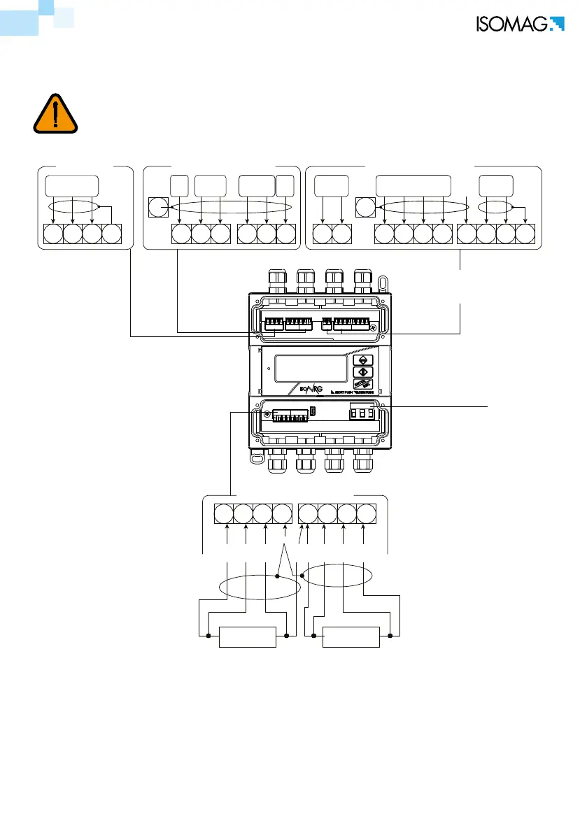
INPUT TERMINAL BLOCK
OUTPUT TERMINAL BLOCK
PULSE
OUTPUT
INPUTS
IN 1: (FV) Vector Fluid
IN 2: (SHW) Sanitary Hot Water
IN 3: (SCW) Sanitary Cold Water
IN 4: Reset o 4° Fluid
POWER SUPPLY
Terminal n° 5 is used only to allow
the right RTD's
wiring (connected in series)
SHIELD
T1+
(EX)
T1-
(EX)
T2+
(EX)
T2-
(EX)
To connect 2 wire probe:
T1: connect the probe to terminal block 2 and 3, bridge on 1-2 and 3-5
T2: connect the probe to terminal block 6 and 7, bridge on 5-6 and 7-8
T1 PROBE
(4 wires)
T2 PROBE
(4 wires)
RTD TERMINAL BLOCK
IN POWER S.
(3V)
4-20 (FV)
17 18 19 20 21 22
COM
IN
_
IN1
4-20
T1+
(M)
T1-
(M)
T2+
(M)
T2-
(M)
OUT22 1COM OUT1
IN2IN3IN4
+
COM
+
0V
+24V
RS485/MBUS
B A
0V
(RT+)(RT-)
26 27 28 16 15 14 13 12 11 10 9
1 2 3 4 5 6 7 8
30 31
9 9
29
WARNING: secure the cables with an additional fastening system placed near the
clamp.
ELECTRICAL CONNECTION
Cable gland PG7: Allowed diameter cables 3-6.5 mm.
 Loading...