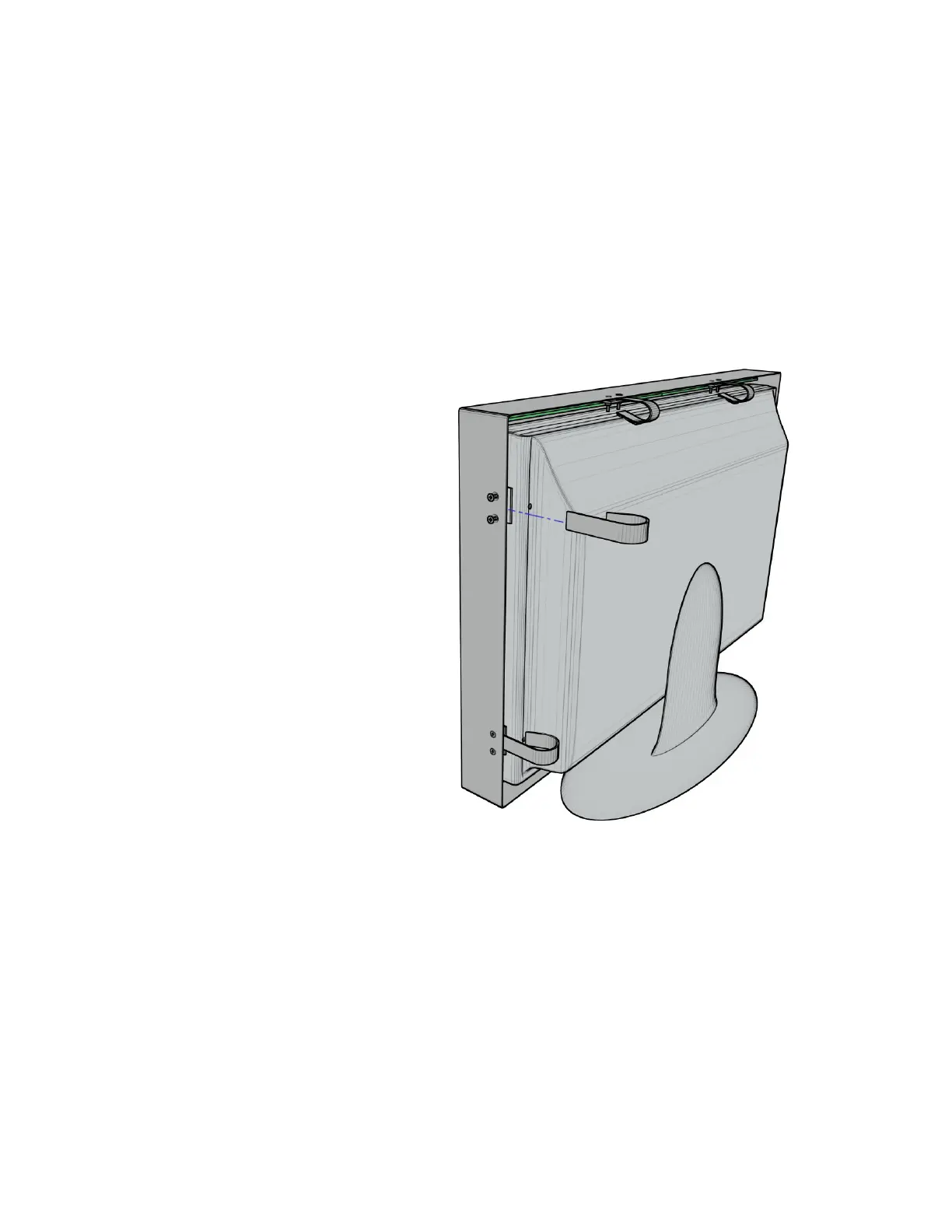
Step 3:
With the touch panel centered on the display, slide the remaining spring brackets into place
under the pinch plates. Evenly tighten the two pinch plate screws.
If the mounting points are towards the extreme corners of the touch panel, the brackets may
pass under the ribbon cables connecting the circuit boards. Use extra caution to ensure the
cables do not become unplugged or damaged while inserting the brackets.
On some models of displays, protrusions, such as a logo or buttons, may block the infrared sensor path and
it may be necessary to loosen the pinch plate screws and slide the touch panel back a fraction of an inch.
 Loading...