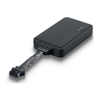
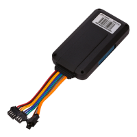
The VT100-L is a 4G-based GPS vehicle tracker designed for comprehensive vehicle supervision and security. It integrates a high-precision GPS+BDS dual-mode positioning module and offers a range of functions for monitoring driving behavior, remote control, and various alarms. Its ultra-mini size facilitates discreet installation, making it suitable for automotive risk control, vehicle supervision, anti-theft, and shared travel industries.
Function Description
The VT100-L provides real-time tracking capabilities, allowing users to monitor vehicle location by time interval or distance. It supports a variety of alarms, including SMS, SOS, external power disconnection, low battery, engine and door status changes, geo-fence breaches, speeding, GPS signal loss, harsh acceleration, harsh deceleration, and harsh turning. Additional features include impact alarm, vibration (towing) alarm, idling alarm, fatigue driving alarm, mileage reports, heading change reports, and FOTA (Firmware Over-The-Air) upgrades. The device also allows for setting ACC ON/OFF time intervals and offers remote fuel/electricity control. Optional features include a buzzer alarm, fuel sensor, fuel theft alarm, and low fuel alarm. It supports dual servers for enhanced reliability.
A key feature is its built-in 16Mb Flash memory, which automatically saves historical positioning data when the device is in an area without network coverage. Once network connectivity is restored, this data is automatically resent to the tracking platform, ensuring no data loss.
Important Technical Specifications
- Size: 80mm x 34mm x 15mm
- Weight: Approximately 48g
- Input Voltage: DC 9-100V/1.5A
- Waterproof Level: IP66
- Inbuilt Battery: 55mAh
- MCU: Cortex-M4, AT32F415CBT7
- Average Standby Power Consumption: 51mA/h
- Operating Temperature: -20°C to 80°C
- Battery Operating Hours: 30 minutes
- LTE/WCDMA/GSM Bands:
- VT100-L CN: LTE-FDD: B1/B3/B5/B8; LTE-TDD: B34/B38/B39/B40/B41; GSM: 900/1800MHz
- VT100-L EU: LTE-FDD: B1/B3/B5/B7/B8/B20; GSM: 900/1800MHz
- VT100-L SA: LTE-FDD: B1/B2/B3/B4/B5/B7/B8/B28/B66
- VT100-L MNG (Cat-M/Cat-NB/GSM(SIM7070G)): Cat-M: B1/B2/B3/B4/B5/B8/B12/B13/B14/B18/B19/B20/B25/B26/B27/B28/B66/B85; Cat-NB: B1/B2/B3/B4/B5/B8/B12/B13/B18/B19/B20/B25/B26/B28/B66/B71/B85; GSM: 850/900/1800/1900MHz
- VT100-L NA-7500 (Cat-1(SIM7500)): LTE-FDD: B2/B4/B12; WCDMA: B2/B5
- VT100-L SA-7500 (Cat-1(SIM7500)): LTE-FDD: B1/B3/B5/B7/B8/B28; WCDMA: B1/B5
- VT100-L GL: LTE-FDD: B1/B2/B3/B4/B5/B8/B12/B13/B14/B17/B18/B19/B20/B25/B26/B27/B28/B31/B39/B66/B71/B85; GSM/GPRS/EDGE: 900/1800MHz
- GPS Module: L76K (GPS+BDS) dual-mode positioning
- GPS Sensitivity: -165dB
- Positioning Accuracy: 2.5 meters
- LED Indicator: 2 LED lights (blue for GPS, green for GSM) indicate status, visible from the outside.
- GSM Antenna: Inbuilt FPC
- GPS Antenna: Built-in ceramic antenna (25 X 25 X 4mm)
- Flash: 16M bit
- Sensor: 3D accelerometer
- Switch: Plug and unplug the SIM card to automatically turn on and turn off the device.
- SIM Card: Nano SIM card
- I/O: 2 Digital inputs (configurable for high/low level trigger, analog input; IN2 defaults to ACC detection), 1 Output, 1 Micro USB. Customizable versions may include 1 Microphone (VT100-L LCN/LEU/LSA versions only) and 1 RS232/TTL.
Usage Features
- Initial Setup: Before first use, connect the tracker's red wire (positive) and black wire (ground) to a 12V or 24V power supply and charge for at least 2 hours.
- SIM Card Installation: Supports 4G SIM cards. Ensure the SIM card has sufficient balance, GPRS function is activated, APN is correct, PIN lock is off, and caller ID display is enabled for location reply calls. The device must be turned off before installing the SIM card by removing the back cover and inserting the SIM card in the correct direction.
- Device Activation: The device starts up and runs when switched ON or connected to an external power supply. LED indicators provide visual feedback on GPS and GSM status.
- GPS Indicator (Blue): OFF (Power OFF/sleep), Flash (starting/restarting), Fast Flash (signal received), Slow Flash (no signal).
- GSM Indicator (Green): ON (incoming/in call), OFF (OFF/sleep), Fast Flash (starting/restarting), Fast Flash (signal received), Slow Flash (no signal).
- Tracking by SMS: Send "0000,800" to the device to receive a text message with a Google Maps link showing the current location.
- Parameter Configuration: Use the "iStartek Parameter Editor_V1.6" software on a computer connected via a USB cable. The software allows for setting server IP, Port, APN, and other parameters. SMS commands (e.g., 100, 102, 109) can also be used for configuration.
- GPS Tracking Platform: Configure server IP, Port, and APN via SMS commands (100, 102, 109) or the iStartek Parameter Editor. Use SMS command 808 to query parameters.
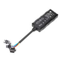
- Power Cable Function Introduction: Detailed pinout and function descriptions are provided for the power cable, including DC In (red, 9-100V), GND (black), IN1 (white, digital input 1, default negative trigger, AD1 input 0-6.6/13.2V), GND (green, connected to SOS button), IN2 (orange, digital input 2, default positive trigger, AD2 input 0-36V), OUT (yellow, open-drain output for remote fuel/engine cut-off), Mic+ (brown), and Mic- (blue) for external microphone.
- Device Installation: Wiring diagrams are provided for both 8-wire and 6-wire standard versions of the VT100-L, illustrating connections to the vehicle battery, ACC, relay, pump, and microphone.
- Analog Input Installation: The device supports connecting up to two voltage-output fuel sensors (capacitive or ultrasonic) to IN1 (white wire) or IN2 (orange wire), configured as AD INPUT. The analog input range is 0-6.6V. After wiring, fuel tank parameters (length, width, height), data source (AD1/AD2), sensor type, fuel stolen liters, fuel stolen time, and low fuel alarm can be configured via the Parameter Editor.
- Ultrasonic Fuel Sensor Installation:
- Connection to VT100-L AD: The green wire of the ultrasonic fuel sensor connects to IN1 (white wire) or IN2 (orange wire) of the VT100-L. The red wire connects to 12V/24V, and the black wire to GND. The sensor's height measurement range is 0-100cm (or 0-250cm optional), with a corresponding voltage output range of 0-5V. Formulas are provided to calculate remaining fuel volume based on AD voltage readings.
- Connection to VT100-L RS232: Requires hardware customization and V113 standard software version or above. The brown/green wire of the ultrasonic fuel sensor connects to RS232-TX (yellow wire) of the VT100-L. The red wire connects to 12V/24V, and the black wire to GND. Configuration is done via Parameter Editor (selecting "Ultrasonic Sensor" and RS232-1/2 as data source) or SMS commands (138, 139, 140, 141, 142).
- Baud Rate Setting: The baud rate of the ultrasonic fuel sensor can be set via its dedicated APP (Bluetooth connection) by entering password "52381", reading current settings, modifying to "115200", and then powering off and restarting the sensor.
- Fuel Theft and Low Fuel Alarms: After wiring, these alarms can be configured via the Parameter Editor or SMS commands. For example, setting a fuel theft alarm to trigger if fuel reduction exceeds 20 liters within 60 seconds, and a low fuel alarm if the volume is less than 10 liters.
- Speed Limiter Installation:
- Measurement: Measure and record the high-level voltage (VH) and low-level voltage (VL) of the gas pedal signal wire when the car is idling and ignition is on.
- Speed Limiter Adjustment: Connect the A01 speed limiter to the vehicle power supply and ground. Adjust its variable resistors until the green signal wire's output voltage equals VH and the gray signal wire's output voltage equals VL.
- Connection to GPS Tracker: Cut the car's gas pedal signal wire. Connect the GPS Tracker VT100-L and speed limiter as per the provided diagram, integrating them into the gas pedal signal line.
- Speed Limit Value Setting: The speed limit value can be set via the Parameter Editor (e.g., "Speeding" parameter) or SMS commands (e.g., "0000, 123, 60" for 60 KM/H, and "0000,212,1,1,22" to trigger output 1 when exceeding the set speed).
Maintenance Features
- Firmware Over-The-Air (FOTA) Upgrade: The device supports FOTA upgrades, allowing for remote updates to its firmware, which can include bug fixes, performance improvements, and new features without physical intervention.
- Historical Data Storage: The built-in 16Mb Flash memory ensures that positioning data is saved during network outages and automatically resent when the network is restored, preventing data loss and facilitating continuous tracking.
- Diagnostic LEDs: The blue (GPS) and green (GSM) LED indicators provide quick visual diagnostics of the device's operational status, helping users identify issues related to GPS signal acquisition or GSM network connectivity.
- Parameter Editor Software: The "iStartek Parameter Editor" software simplifies configuration and troubleshooting by providing a graphical interface for setting various device parameters.
- SMS Commands: A comprehensive set of SMS commands allows for remote configuration, query of parameters, and control of the device, which is useful for maintenance and adjustments without direct physical access.
- Technical Support: For any further questions or issues, users are encouraged to contact info@istartek.com for support.