I I I I I I I I I I I I I I I I I I I I I I I I I I I I I I I I I I I I I I I I I I I I I I I I I I I I I I I I II I I I I I I II
GENERAL INFORMATION 1-l 1
ified angle 0
Coinciding line
Tighten
D
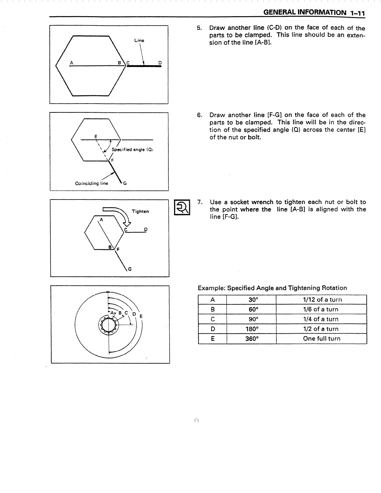
5. Draw another line (C-D) on the face of each of the
parts to be clamped. This line should be an exten-
sion of the line [A-B].
6. Draw another line [F-G] on the face of each of the
parts to be clamped. This line will be in the direc-
tion of the specified angle (Q) across the center [E]
of the nut or bolt.
Example: Specified Angie and Tightening Rotation
A
r
30
0
l/12 of a turn
B 60
0
l/6 of a turn
.
C
90
0
l/4
of a
turn
D 180°
E
360’
l/2 of a turn
One full turn -
 Loading...


