HOLD
1
MAX /MIN
2
UNIT
3
LIGHT
5
VEL /FLOW
4
READ
7
RST /CLR
8
REC
9
SAM PLE
ARE A
0
START /NEXT
OPT ION
ENT ER
C/ F
6
-04- -05-
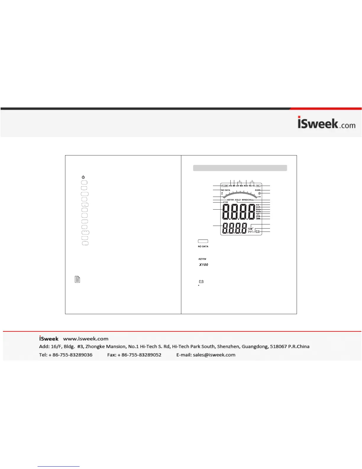
1. :Air flow symbol
2. :No data store symbol
3. Dynamic indicator bar of velocity or air flow
4. :Enter duct area values symbol
5. :Air multiplier
6. Wind velocity and air flow display area
7. Duct area display area/Wind temperature display
8. :Low battery icon
9. :Indicating duct area in square feet
when in flow function ; ℉ is used to indicate
wind temperature in metric;
FLOW
1
2
3
4
5
6
7
8
9
10
11
12
13
14
15
16
17
19
18
20
21
22
27 26 25 24 23
FT
2
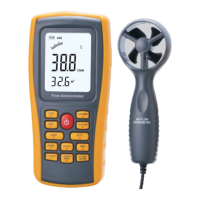
1). USB interface
2). LCD display
3). : ON/ OFF key
4). :Data holding key
5). :Unit transform key
6). :Backlight on/off key
7). :Data read key
8). :Measuring key for average value of wind flow
9). :Reset key in READ mode/clear recorded
10). :Duct area input and sampling time setting key
11). :Wind flow AVG 2/3 MAX and figure input
12). :Data record key
13). :Temperature unit switch
14). :Wind velocity/flow transform key
15). :Max/Min value switch
16). Connecting wire
17). Fan
NOTE:
Aforesaid key function descriptions is brief
introduction.
pls read operation instructions parts for details.
LCD Dis play