Device description
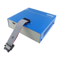
The top face of the iC5700 features two key areas; the DTM connectors A and the indicator
lights B.
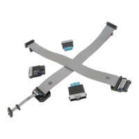
A – Debug Trace Module (DTM) provides two connectors, marked #1 and #2. These
connectors are the interface to the target microcontroller. Depending on the target
microcontroller debug features, the supplied ribbon-cables will need to be connected to either
connector #1 only or connectors #1 and #2.
B – The indicator lights provide the status of the iC5700 hardware as follows:
Power Indicator – Green
§
On – Powered on
§
Off – Powered off
R - Running Indicator – Red
§
On – Target
microcontroller is
executing code
§
Off – Target
microcontroller is
halted
F - Free Indicator – Yellow
§
On – BlueBox is
available for a
connection from a
host PC
§
Off – Active
connection to the
BlueBox from a host
PC exists
The front face of the iC5700 features:
C – The grounding socket (marked GND) should be used, together with the supplied Grounding
Wire to create an electrical connection between the iC5700 and the target circuitry. The socket
is suitable for a 2 mm Multi Contact Plug (also known as a Banana Plug) if building a longer
or a replacement cable on your own.
D – The FNet Port provides an interface for the iSYSTEM’s range of IOM6 accessories. See also
Accessories chapter.
The rear face of the iC5700 features the remaining connectors as follows:
E – 10/100 Ethernet Socket
G – Power Supply Socket
The socket and plug are latching to stop the
plug from being accidentally pulled out of the
socket.
To remove the power plug from the socket,
always pull gently of the sleeve of the plug
and never on the wire.
F – USB 3.0 Socket
It is highly recommended to use the supplied
USB 3.0 cable delivered with your BlueBox as
it has been confirmed to fulfill the maximum
USB 3.0 transfer rate (5Gbit/s). Use of
alternate cables must be undertaken at your
own risk.