Do you have a question about the iSystem iC5000 and is the answer not in the manual?
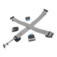
Lists all available debug adapters with their ordering codes for iC5000/iC5700.
Details the signal pin assignments for the 20-pin 2.54mm ARM debug connector.
Covers potential hardware failures from mismatches and connector types.
Explains the TI-specific pinout and the function of the SYSTEM RESET jumper.
Specifies the 14-pin 2.54mm connector for target connection.
Details the signal pin assignments for the 20-pin 2.54mm Cortex-M debug connector.
Describes resettable fuses and the standard 20-pin connector.
Details the signal pin assignments for the 14-pin 2.54mm ARM debug connector.
Covers resettable fuses and the 14-pin connector specifications.
Details the pin assignments for the 20-pin 1.27mm AMPMODU Cortex-M connector.
Explains trace signals and fuse/resistor protection mechanisms.
Specifies the 20-pin AMP connector for target connection.
Details the pin assignments for the 38-pin Mictor ETMv1 ARM debug connector.
Identifies blue colored signals as parallel trace signals.
Details the pin assignments for the 38-pin Mictor ETMv3 ARM debug connector.
Covers resettable fuses and serial resistor protection for debug signals.
Specifies the 38-pin Mictor connector for target connection.
Explains trace data line capabilities and target configuration for MIPI.
Notes signal naming conventions and refers to external documentation.
Specifies the 60-pin MIPI connector for target connection.
Details the signal pin assignments for the 60-pin MIPI debug connector.
Notes adapter compatibility with other debug adapters.
Details the signal pin assignments for the 10-pin 1.27mm Cortex-M debug connector.
Describes resettable fuses protecting debug signals against overcurrent.
Discusses two connector types for the 10-pin adapter.
Compares 'Standard' and 'Strain relief' connector types for robustness.
Provides order code for spare cable and discusses optional longer cables.
Details the custom pin assignments for the 10-pin 1.27mm Cortex-M debug connector.
Explains the jumper settings for TRST, RTCK, or KEY functions on pin 7.
Covers resettable fuses and specifies the 10-pin 1.27mm connector.
Details the signal pin assignments for the 20-pin 1.27mm Cortex-M debug connector.
Covers resettable fuses and serial resistor protection for debug signals.
Discusses two connector types for the 20-pin adapter.
Discusses connector types and recommends the robust strain relief option.
Compares 'Standard' and 'Strain relief' connector types for robustness.
Provides order code for spare cable and discusses optional longer cables.
Details the pin assignments for the 20-pin 1.27 x 2.54mm Compact TI-20 debug connector.
Covers fuse protection and explains the function of Jumpers J1 and J2.
Specifies the 20-pin 1.27 x 2.54mm connector for target connection.
Details the custom pin assignments for the 16-pin 1.27mm ARM debug connector.
Describes resettable fuses protecting debug signals against overcurrent.
Specifies the 16-pin 1.27mm connector for target connection.
Details the pin assignments for the 14-pin 2.54mm MPC5xxx/SPC5 debug connector.
Covers resettable fuses and lists mandatory microcontroller pins.
Explains Pin 8 functionality and the purpose of Jumpers J1 and J2.
Explains JTAG/DAP support and details the 10-pin Bosch ECU14 Tricore target pinout.
Specifies the 14-pin 2.54mm connector for target connection.
Explains Jumper J2 function and adapter compatibility with other units.
Discusses standard and shorter cable lengths for the adapter.
Explains the function of Jumper J2 for Nexus SYNC in trace capture.
Details the pin assignments for the 38-pin Mictor MPC5xxx/SPC56 Nexus debug connector.
Covers resettable fuses and serial resistor protection for debug signals.
Specifies the 38-pin Mictor connector for target connection.
Explains connection to the 38-pin Mictor adapter for Nexus interface.
Warns about potential connection issues with the 50-pin ERF8 connector.
Details the signal pin assignments for the 50-pin ERF8 MPC5xxx Nexus debug connector.
Identifies blue colored signals as parallel trace signals.
Explains the function of Jumper J2 for Nexus SYNC in trace capture.
Details the pinout and covers fuse protection for the 50-pin ERF8 adapter.
Identifies blue colored signals as parallel trace signals.
Details the signal pin assignments for the 16-pin 2.54mm Infineon JTAG debug connector.
Covers resettable fuses and lists mandatory Infineon JTAG pins.
Specifies the 16-pin 2.54mm connector for target connection.
Explains JTAG/DAP support and details the 10-pin Bosch ECU14 Tricore target pinout.
Identifies pin 1 and explains the function of jumpers J1 and J2.
Details the signal pin assignments for the 10-pin 1.27mm MEDC17 debug connector.
Covers resettable fuses and lists mandatory pins for MEDC17 connection.
Specifies the 10-pin 1.27mm connector for target connection.
Details the signal pin assignments for the 6-pin 2.54mm Infineon I2C debug connector.
Covers resettable fuses and provides emulation mode notes for the MCU.
Describes debug download steps and limitations in debug mode.
Specifies the 6-pin 2.54mm connector and notes on 4-pin extension.
Explains Jumper J1 settings for normal debug or Hot Attach operations.
Details the signal pin assignments for the 10-pin 1.27mm Infineon DAP debug connector.
Discusses two connector types for the 10-pin adapter, 'Standard' and 'Strain relief'.
Compares 'Standard' and 'Strain relief' connector types for robustness.
Provides order code for spare cable and discusses optional longer cables.
Explains Jumper J1 settings for normal debug or Hot Attach operations.
Details the signal pin assignments for the 22-pin ERF8 Aurix debug connector.
Covers resettable fuses and specifies the 22-pin ERF8 connector.
Covers resettable fuses protecting debug signals against overcurrent.
Specifies the 22-pin ERF8 connector and its matching target part.
Details the signal pin assignments for the 20-pin 2.54mm V850/RH850 debug connector.
Describes resettable fuses and serial resistor protection for debug signals.
Details the signal pin assignments for the 14-pin 2.54mm RH850 debug connector.
Describes resettable fuses and serial resistor protection for debug signals.
Details the signal pin assignments for the 10-pin 1.27mm RH850 EPS debug connector.
Describes resettable fuses and serial resistor protection for debug signals.
Discusses two connector types for the 10-pin adapter.
Compares 'Standard' and 'Strain relief' connector types for robustness.
Provides order code for spare cable and discusses optional longer cables.
Explains the function of Jumper J1 to isolate the EVTI input pin.
Details the signal pin assignments for the 38-pin Mictor RH850/F1H Nexus debug connector.
Specifies the 38-pin Mictor connector for target connection.
Covers resettable fuses and serial resistor protection for debug signals.
| Brand | iSystem |
|---|---|
| Model | iC5000 |
| Category | Measuring Instruments |
| Language | English |