5
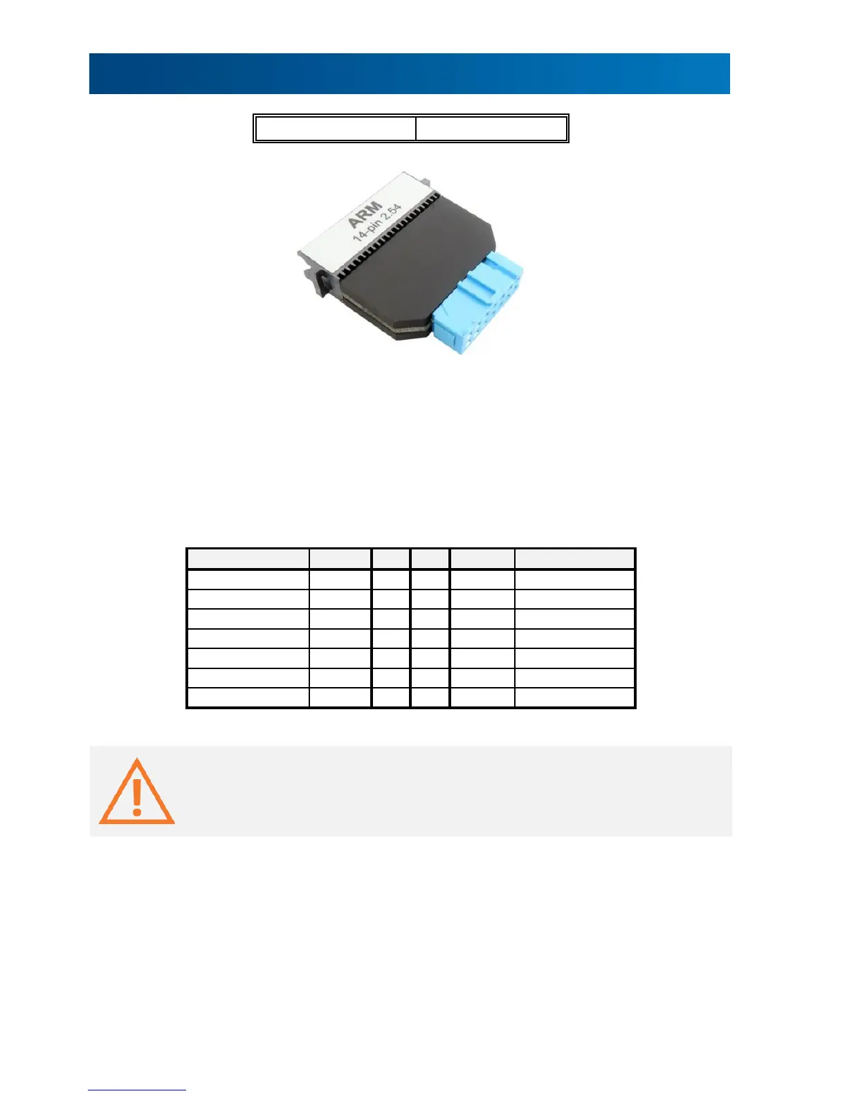
14-pin 2.54mm ARM Debug Adapter
This debug adapter is used to connect the iC5000 and the iC5700 BlueBox to the Cortex-A, the
Cortex-R, the ARM7 and the ARM9 based target. It’s used to connect to the embedded target
featuring a 14-pin 2.54 mm pitch target debug connector with the ARM pinout.
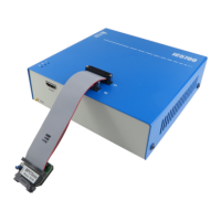
The debug adapter connects to the 25cm 40-pin ribbon cable coming from the BlueBox and to
the target debug connector on the other side. Refer to the BlueBox User Manual for more
details on connecting the debug adapter.
The following pinout is valid on the target side:
When connecting the BlueBox to the new embedded target for the first time, double
check that the debug adapter pinout matches with the target debug connector. Note
that a mismatch can result in a hardware failure.
The debug adapter features resettable fuses on all pins. These fuses protect debug signals
against overcurrent and cycle back to a conductive state after the excessive current fades
away.
The debug adapter connects to the target via a 14-pin 2.54 mm connector, for example
Yamaichi FAS-1401-2101-2-0BF. A target should feature a matching part, for example WÜRTH
ELEKTRONIK 61201421621.