33
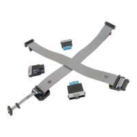
10-pin 1.27mm Tricore ECU14 Debug Adapter
This connector has been defined by Bosch and supports the JTAG and the DAP debug interface.
This debug adapter is used to connect the iC5000 and the iC5700 BlueBox to Infineon TriCore
and XC2000/XC166 based target featuring a 10-pin 1.27mm pitch target debug connector with
Bosch ECU14 pinout.
This debug adapter supports only the JTAG debug interface. It doesn’t support the DAP
debug interface.
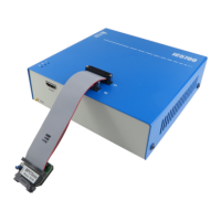
The debug adapter connects to the 25cm 40-pin ribbon cable coming from the BlueBox and to
the target debug connector on the other side. Refer to the BlueBox User Manual for more
details on connecting the debug adapter.
The following pinout is valid on the target side:
10-pin Bosch ECU14 target pinout
When connecting the BlueBox to the new embedded target for the first time, double
check that the debug adapter pinout matches with the target debug connector. Note
that a mismatch can result in a hardware failure.