34
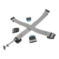
10-pin 1.27mm TriCore ECU14 Debug Adapter features resettable fuses on all connected pins.
These protect debug signals against overcurrent and cycle back to a conductive state after the
excessive current fades away. Mandatory pins on the microcontroller side are the TMS, the
TDO, the TDI, the ~TRST, the TCLK and the ~RESET. The USERIO signal is used optionally.
Pin 1 position
The pin 1 position is marked with a small white square on the PCB. Additionally the pin is
marked with a number 1 directly on the debug adapter target connector from revision C1 on.
Jumper J1
The jumper J1 has been put on the debug adapter only for making provision for future
extensions of the “ECU14” target connection.
The USERIO signal (target debug connector pin 7) is connected to the BlueBox output (J1 in the
position 1-2) or to the BlueBox input (J1 in the position 2-3). Currently the signal has no
functionality and consequentially the J1 is not populated.
Jumper J2
The jumper J2 is optional and by default not populated. It connects 10k pull-down resistor to
the USERIO pin when bridged.
The jumper has been introduced for a custom target, where the target watchdog gets disabled
during the debugging, when low level at the USERIO signal (target debug connector pin 7) is
detected.
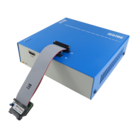
The debug adapter connects to the target via a 10-pin 1.27mm connector, Samtec SFM-105-01-
S-D. A target should feature a matching part, for example Samtec TFM-105-01-L-D.