EasyManuals Logo

iSystem iC5000 User Manual

iSystem iC5000
54 pages
To Next Page IconTo Next Page
To Previous Page IconTo Previous Page
Page #18 background imageLoading...
Page #18 background image
15
20-pin 1.27mm Cortex Debug Adapter
Ordering code
IC50118-2
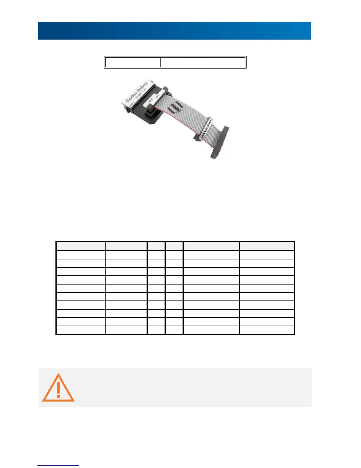
This adapter is used to connect the iC5000 and the iC5700 development system to the Cortex-
M based target. It’s used to connect to the embedded target featuring a 20-pin 1.27mm target
debug connector with the Cortex-M pinout.
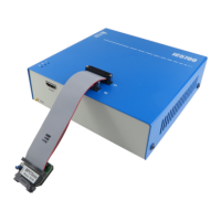
The debug adapter connects to the 25cm 40-pin ribbon cable coming from the BlueBox and to
the target debug connector on the other side. Refer to the BlueBox User Manual for more
details on connecting the debug adapter.
The following pinout is valid on the target side:
Signal direction
Signal
Pin
Pin
Signal
Signal direction
I
VTref
1
2
SWDIO / TMS
I/O / O
GND
3
4
SWCLK / TCK
O
GND
5
6
SWO / TDO
I
KEY
7
8
NC / TDI
O
GND
9
10
nSRST
I/O
NC_CAPGND
11
12
TRCLK
I
NC_CAPGND
13
14
TRD0
I
GND
15
16
TRD1
I
GND
17
18
TRD2
I
GND
19
20
TRD3
I
20-pin Cortex-M pinout
Blue colored signals are parallel trace signals.
When connecting the BlueBox to the new embedded target for the first time, double
check that the debug adapter pinout matches with the target debug connector. Note
that a mismatch can result in a hardware failure.

Other manuals for iSystem iC5000

Questions and Answers:

Question and Answer IconNeed help?

Do you have a question about the iSystem iC5000 and is the answer not in the manual?

iSystem iC5000 Specifications

General IconGeneral
BrandiSystem
ModeliC5000
CategoryMeasuring Instruments
LanguageEnglish

Related product manuals