Jumper J2 was introduced with the debug adapter revision C1. Previous versions A1, A2,
B1 and D1 don’t provide this jumper.
The debug adapter connects to the target via a 14-pin 2.54 mm connector, for example
Yamaichi FAS-1401-2101-2-0BF. A target should feature a matching part, for example WÜRTH
ELEKTRONIK: 612 014 216 21.
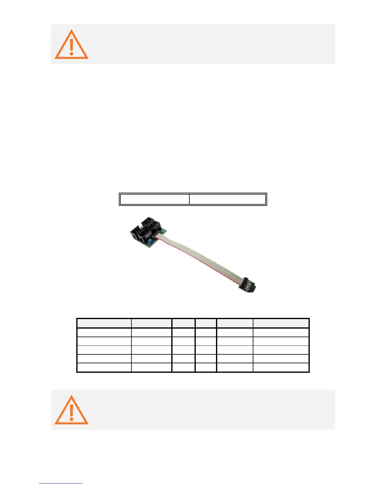
ECU14 JTAG 10-pin 1.27mm Adapter
The ECU14 connector standard has been defined by Bosch and can feature either the JTAG or
the DAP debug interface.
An adapter connecting at the end of the 14-pin 2.54mm MPC5xxx Debug Adapter is available
for the MPC5xxx/SPC5 embedded target featuring the ECU14 10-pin 1.27mm connector and
must be ordered separately under the IAMPC_TC2ECU14 ordering code. Toward the BlueBox
the adapter features 14-pin 2.54 mm male connector featuring the MPC5xxx/SPC5 JTAG debug
interface and 16-pin 2.54 mm male connector featuring Infineon JTAG debug interface.
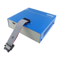
When connecting the BlueBox to the new embedded target for the first time, double
check that the debug adapter pinout matches with the target debug connector. Note
that a mismatch can result in a hardware failure.