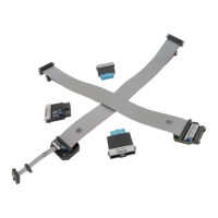
This debug adapter is used to connect the iC5000 and the iC5700 BlueBox to Freescale
MPC5xxx or ST SPC56 based target featuring a 50-pin Samtec ERF8 target debug connector
with the MPC5xxx Nexus pinout.
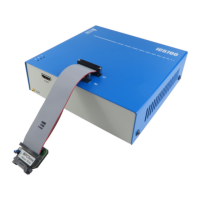
The debug adapter connects to the BlueBox through the two ribbon cables and to the target
debug connector on the other side. Refer to the BlueBox User Manual for more details on
connecting the debug adapter.
It has been noticed that the 50-pin Samtec ERF8 target connector may not always
provide good mechanical stability in a vertical direction which can in worst case yield an
unreliable debug connection. Special care must be taken when connecting this debug
adapter to the target to prevent potential connection problems.
Jumper J2 (EVTIN)
Under some circumstances it can happen that the debugger cannot find any absolute program
counter message in the analyzed Nexus trace stream. Consequentially, the program trace
reconstruction fails and errors or nothing gets displayed in the trace window. To avoid such
situations, the BlueBox can feed periodic signal to the EVTIN CPU pin connecting to the on-chip
Nexus trace engine, which then periodically generates and broadcasts program counter
synchronization messages.
In order to use this feature, the jumper J2 must be bridged and the ‘Force periodic Nexus SYNC’
option in the ‘Hardware/emulation Options/CPU Setup/Nexus’ tab must be checked in
winIDEA
TM
. Refer to iSYSTEM ‘Freescale MPC5xxx & ST SPC56 Family On-Chip Emulation’
technical notes document for more details on the ‘Force periodic Nexus SYNC’ option use.
Note that the EVTI (Nexus Event In) CPU pin may be shared with other CPU functionalities. For
instance, on the MPC5516 the same pin can operate as the GPIO, the EBI read/write or the
EVTI. Whenever the CPU pin is configured and used for the EVTI alternate operation, the J2
must not be populated in order to prevent electrical conflicts.