Typically there is no need to use the ‘Force periodic Nexus SYNC’ functionality unless a
specific application code is traced, which does not generate messages containing
absolute program counter information. As long as the user has no problems with the
trace use, it is recommended to keep the jumper J2 disconnected.
The following pinout is valid on the target side:
50-pin Samtec ERF8 MPC5xxx Nexus target pinout
Blue colored signals are trace signals.
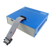
When connecting the BlueBox to the new embedded target for the first time, double
check that the debug adapter pinout matches with the target debug connector. Note
that a mismatch can result in a hardware failure.
50-pin ERF8 MPC5xxx Nexus 16-bit Debug Adapter features resettable fuses on pins 2, 4, 6, 8,
10, 12, 16 and 20. These protect debug signals against overcurrent and cycle back to a
conductive state after the excessive current fades away. All other signals are protected via the
47 ohm serial resistor.
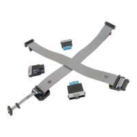
The debug adapter connects to the target via a 50-pin Samtec connector, Samtec ERM8-025-
01-L-D-EM2. A target should feature a matching part, for example Samtec ERF8-025-05.0-L-DV
in the SMT technology.